
11 ITEMSVIEW CART


Total: 697.00

Expert Support
Full Speed
100% Working
30 USD
Contents:
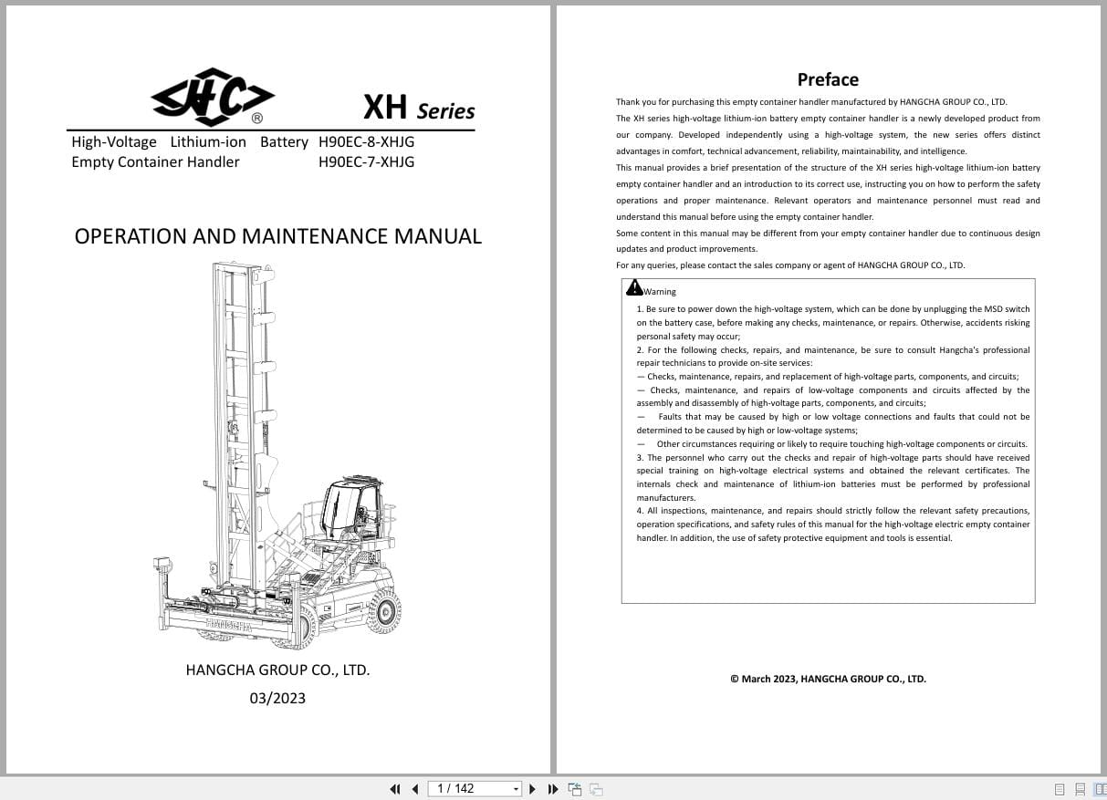
Preface
I. Lithium-Ion Battery
1.1 Precautions
1.2requirements On Assembly Protection And Tools
1.3 Structure And Size
1.4 Structure Of The Lithium-Ion Battery
1.5 Working Principle Of The Lithium-Ion Battery
1.6 Disassembly And Assembly Of The Lithium-Ion Ba
1.7 Voltage Detection Of The Battery Discharge
1.8 Lithium-Ion Battery Common Fault Diagnosis
Ii. Driving System
2.1 Overview Of The Driving System (Stand-Up Type)
2.2 Disassembly And Assembly Of The Driving System
2.2.1 Removing The Driving System From The Truck
2.2.2 Disassembly Of The Driving Unit
2.3 Drive Motor
2.4 Steering Motor
2.5 Transmission
Fig. 2-5 Gearbox Exploded Diagram
1. Shim
2. Tapered Roller Bearing
3. Tapered Roller Bearing
4. Washer
5. Oil Seal
6. Bushing
7. Driving Spiral Bevel Gear
8. Driven Spiral Bevel Gear
9. Washer
10. Adjusting Shim
11. O-Ring
12. Cover
13. Hexagon Socket Cap Screw
14. Tapered Roller Bearing
15. Tapered Roller Bearing
16. Driven Gear
17. Nut
18. Drive Gear
19. Shim
20. Housing
21. Sealing Gasket
22. Hexagonal Socket Screw Plug
23. Magnetic Screw Plug
24. Output Flange
25. Double-Threaded Stud
26. Nameplate
27. Locknut
28. Hexagonal Nut With Flange
29. Steering Gear Ring
30. Cylindrical Pin
31. Hexagon Socket Cap Screw
32. Vent Plug
33. Hexagon Socket Cap Screw
34. Hexagon Socket Cap Screw
35. Hexagon Socket Cap Screw
36. O-Ring
37. Plastic Plug Cover
38. Steering Bearing
2.5.2 Main Technical Parameters Of The Gearbox
2.5.3 Precautions For Installation And Use
2.5.4 Gearbox Disassembly
1. Remove The Driving Unit From The Truck Body And
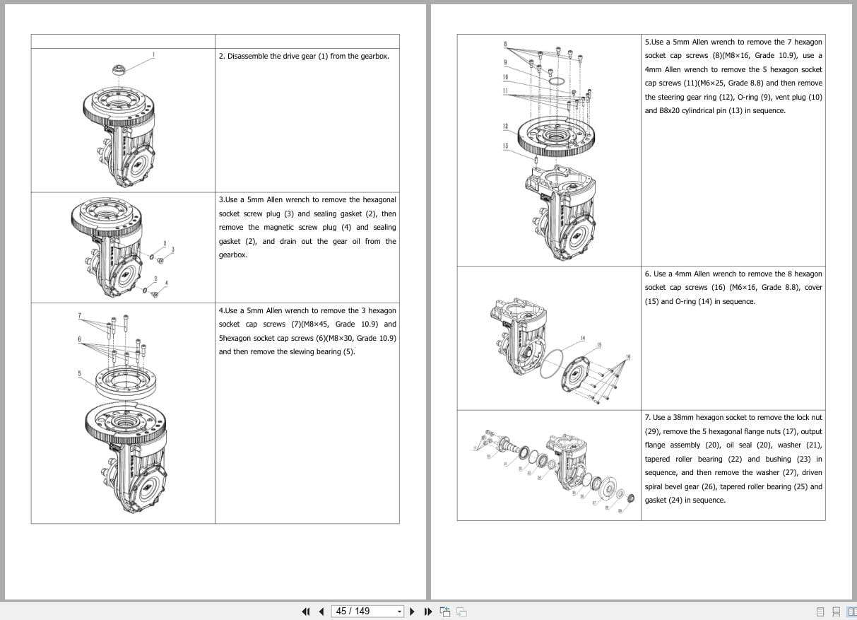
2. Disassemble The Drive Gear (1) From The Gearbox
3.Use A 5mm Allen Wrench To Remove The Hexagonal S
4.Use A 5mm Allen Wrench To Remove The 3 Hexagon S
5.Use A 5mm Allen Wrench To Remove The 7 Hexagon S
6. Use A 4mm Allen Wrench To Remove The 8 Hexagon
7. Use A 38mm Hexagon Socket To Remove The Lock Nu
8. Remove The 5 Double-Threaded Studs (18).
9. Use A 24mm Hexagon Socket To Remove The Nut (30
10. This Completes The Gearbox Disassembly.
2.5.5 Gearbox Assembly
2.5.6 Gearbox Fault Analysis
2.6 Electromagnetic Brake
Keep The Brake Free From Greasy Dirt During Mount
Iii. Steering Control System
3.1 Overview Of The Steering Control System
3.2 Steering Control System Structure
3.3 Disassembly And Assembly Of The Steering Contr
3.4 Control Handle
3.5 Modular Internal Handle Removal
3.6 Hand Shank Common Faults
Iv. Wheel System
4.1 Overview Of The Wheel System
4.2 Disassembly And Assembly Of The Wheel System
4.3 Auxiliary Wheel Height Adjustment
V. Truck Body System
5.1 Overview Of The Truck Body System
5.2 Guardrail Assembly
5.3 Guardrail Disassembly And Assembly
5.4 Floor Assembly
5.5 Disassembly And Assembly Of The Floor Assembly
5.6 Disassembly And Assembly Of The Hood Cover.
Vi. Hydraulic System
6.1 Hydraulic System Structure
6.2 Hydraulic Unit
6.4 Parameters Of The Hydraulic Unit
6.5 Pressure Adjustment Of The Main Safety Valve
6.6 Fault Diagnosis And Troubleshooting
Vii. Lifting System (Stacker)
7.1 Parameters For Adjustment
7.3.1 Chain
7.3.2 Mast
7.3.3 Left And Right Lifting Cylinder, Free Liftin
Viii. Controller
8.1 Overview
8.2 Table Of Faults And Troubleshooting
8.3 Fault Diagnosis
8.3.1 Controller Overcurrent Fault
8.3.2 Current Sensor Fault
8.3.3 Precharge Fault
8.3.4 Severe Under-Temperature Of The Controller
8.3.5 Severe Over-Temperature Of The Controller
8.3.7 Severe Over-Voltage Of The Busbar
8.3.8 Controller Over-Temperature Alarm
8.3.10 Motor Over-Temperature Alarm
8.3.11 Motor Temperature Sensor Fault
8.3.12 Brake Failure
8.3.13 Ab Pulse Feedback Cross Self-Test Fault
8.3.14 Phase Loss Of The Motor
8.3.15 Main Contactor Stuck
8.3.16 Main Contactor Pick-Up Failure
8.3.17 Motor Overspeed
8.3.18 Severe Over-Temperature Of The Motor
8.3.19 Eeprom Fault
8.3.20 Can Bus Abnormality
8.3.21 Position Command Analog Fault
8.3.22 Resolver Encoder Wire Disconnection
8.3.23 Zero Timeout
8.3.23 Bipolar Zero Test Failure
8.3.24 Can Communication Loss
8.3.25 Motor Stall
8.3.26 Controller Hardware Fault
8.3.27 Motor Brake Failure
Ix. Electrical System
8.1. Instruments
8.2 Emergency Stop Switch
X. Schematic Diagrams
10.1 Braking Schematic Diagram
10.2 Hydraulic Schematic Diagram
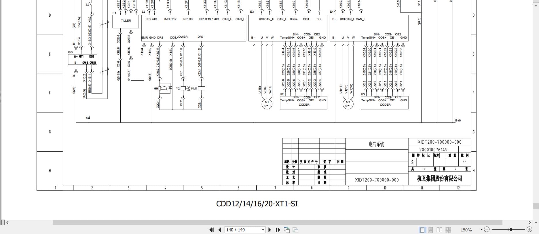
10.3 Electrical Schematic Diagram
Xi.Bolts Tightening Torque Table
REALEASE :
REALEASE :
REALEASE :
REALEASE :

REALEASE :
REALEASE :

REALEASE :
REALEASE :
REALEASE :
REALEASE :
REALEASE :
REALEASE :

REALEASE :
REALEASE :
REALEASE :
REALEASE :
 Automotive - Heavy Equipment - Truck & Bus - Forklift - Crane