
4 ITEMSVIEW CART


Total: 190.00
Expert Support
Full Speed
100% Working
30 USD
Contents:
1. Lithium-Ion Battery
1.1 Instructions And Precautions For Use
1.2 Structure And Size
1.3 Definition Of Charging Socket Interfaces
1.4 Daily Maintenance
1.5 Internal Components
1.6 Structure Of The Lithium-Ion Battery
1.7 Fault Diagnosis
1.8 Battery Maintenance
1.9 Battery Common Fault Diagnosis
2 Transmission System
2.1 Overview Of The Transmission System
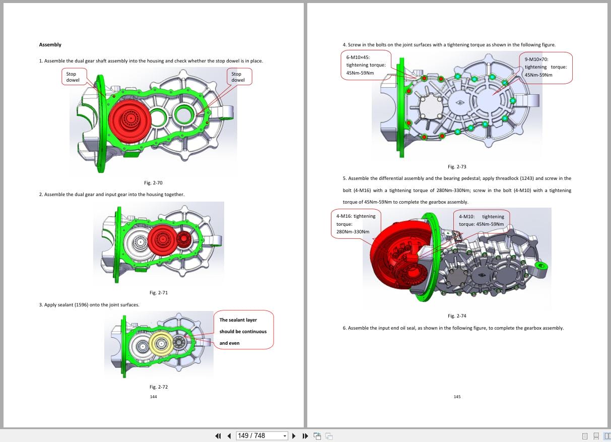
2.2 Transmission System Disassembly
2.3 Drive Axle
2.4 Transmission
2.5 Tires
3 Steering Device And Steering Axle
3.1 Overview
3.2 Steering Device
3.3 Steering Axle
4. Braking System
4.1 Overview
4.2 Service Brake And Brake Master Cylinder
4.3 Hand Brake
4.4 Service Brake
Park The Forklift On A Level And Solid Surface, Th
Use A Hydraulic Jack Near The Front Wheel To Lift
1.Remove The 6 Hub Nuts (1) From The Wheel Rim And
Fig. 4-13
Fig. 4-14
4.Pull Out The Half Shaft, Loosen The 2 Screws (It
Fig. 4-15
Fig. 4-16
Fig. 4-17
Fig. 4-18
Fig. 4-19
Fig. 4-20
Fig. 4-25
Fig. 4-26
Fig. 4-27
4.4.2.3 Install
Fig. 4-28
Fig. 4-29
Fig. 4-30
4.Install The Brake Cable Assembly And Clip The E
Fig. 4-31
Fig. 4-32
Fig. 4-33
7.Install The Left Gap Adjuster Assembly (9) And
Fig. 4-34
Fig. 4-36
5.Unscrew The 2 Screws.
Fig. 4-37
6.Install The Locking Piece So That Its Hole Match
7.Screw On The Brake Washer. (The Locating Pin Of
Fig. 4-38
8.Turn The Hub Forward And Backward For 2-3 Turns,
Fig. 4-39
9.Measure The Axial Clearance Of The Hub With (4)
Fig. 4-40
10.Use The Locating Pin (5) To Guide And Position
Fig. 4-41
11.Tighten The 6 Screws.
12.Turn The Wheel Clockwise While Pressing The Bra
13.Remove The Hydraulic Jack And Wood Pads. Start
4.5 Electromagnetic Brake(Optional)
4.6 Fault Diagnosis And Troubleshooting
5. Truck Body
5.1 Overview
5.2 Dashboard Assembly
5.3 Machine Hood And Floor Assembly
5.4 Battery Clamping Device
5.5 Counterweight
5.6 Overhead Guard
5.7 Seat
6. Hydraulic System
6.1 Overview Of Hydraulic System
6.2 Oil Pump Device
6.3 Multi-Way Valve
6.5 Hydraulic Oil Tank
6.6 Electromagnetic Proportional Control Valve (O
6.7 Priority Valve (Optional Thumb Switch)
6.8 Steering Gear
Cpd20-Xexy2ha-Si
Cpd30-35-38-Xey2-Si
Cpd30-35-38-Xey2h1-Si
Cpd20-25-Xey2-Si
Cpd20-25-Xey2h-Si
Cpd30-35-38-Xey2h-Si
-202403
Cpd30-35-38-Xey2ha-Si
202403-
Cpd40-45-Xey2-Si
Cpd50-Xey2-Si
Cpd50-Xexy2-Si
Cpd40-45-Xey2-Sigw
Cpd50-Xey2-Sigw
6.9 Common Fault Diagnosis And Troubleshooting
7. Motor
7.1 Traction Motor
7.2 Oil Pump Motor
7.3 Motor Maintenance
7.4 Precautions For Disassembly
7.5 Replacement Of The Speed Sensor And Temperatu
8. Mast
8.1. Overview
8.2 Parameters For Adjustment
8.3 Main Structural Components Of The Lifting Asse
8.4 Disassembly, Assembly And Adjustment Of The L
8.5 Fault Diagnosis And Troubleshooting
9. Controller
9.1 Overview
9.2 Features
9.3 Traction Controller Fault Codes (E1 Series)
9.4 Troubleshooting For Traction Controller Fault
9.5 Oil Pump Controller Fault Codes (E3 Series)
9.6 Troubleshooting For Oil Pump Controller Fault
9.7 Checks And Adjustment For The Parameters Of T
9.8 Disassembly And Assembly
10 Electrical Components
10.1 Dashboard
10.2 Lighting System
10.3 Switch
10.4 Fuse
10.5 Others
10.6 Common Faults And Troubleshooting Of The Ele
Whether The Angle Sensor Line Is Disconnected
Yes: Line Problem, Repair Line.
No: Unplug The Angle Sensor And Measure Whether Th
Yes: The Angle Sensor Is Damaged. Replace The Angl
No:If The Power Supply Cable Of The Angle Sensor O
11. Schematic Diagrams
11.1 Braking Schematic Diagram
11.2 Hydraulic Schematic Diagram
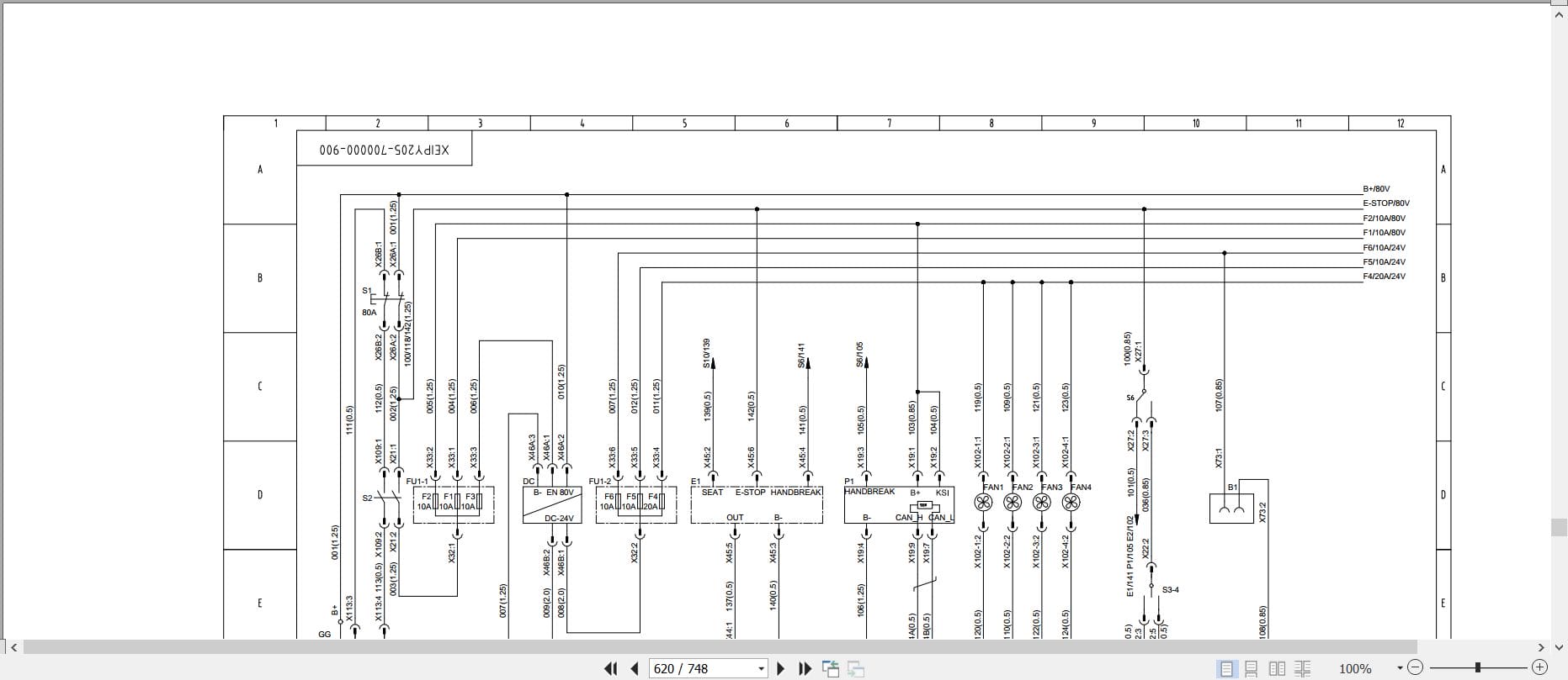
11.3 Electrical Schematic Diagram
12. Cab
12.1 Cab Overhead Guard
12.2 Cab Door Assembly
12.3 Cab Rear Window Assembly
12.4 Cab Front Windshield Assembly
12.5 Cab Fan
12.6 Electrical Schematic Diagram For The Cab
13 Main Accessories
13.1 Thumb Switch
13.2 Attachments
14. Bolts Tightening Torque Table
REALEASE :
REALEASE :

REALEASE :
REALEASE :
REALEASE :
REALEASE :
REALEASE :
REALEASE :
REALEASE :
REALEASE :
REALEASE :
REALEASE :
REALEASE :
REALEASE :

REALEASE :
REALEASE :
 Automotive - Heavy Equipment - Truck & Bus - Forklift - Crane