
0 ITEMSVIEW CART

✓
Expert Support
✓
Full Speed
✓
100% Working
Haulotte Articulating Boom HA16 E to HA46 E PRO Service Repair Manual 4001296660 10.2025 EN
Size: 65.63 MB
Format: PDF
Language: English
Brand: Haulotte
Type of Machine: Articulating Boom
Type of Manual: Service Manual, Repair Manual, Wiring Diagram, Hydraulic Diagram
Model: Haulotte HA16 E HA46 E, HA16 E PRO HA46 E PRO Touch Screen Display Articulating Boom
Part Number: 4001296660
Publication Date: 10.2025
Number of Pages: 408 Pages
50 USD
- Description
Description
Contents:
Responsibilities And Commitments
1 Foreword
2 Responsibilities
2.1 Owner’s Responsibility
2.2 Technician’s Responsability
3 Haulotte® Commitments
3.1 Haulotte Services®
3.2 Training
3.3 Product Information
4 Conditions Of Warranty
Safety
1 General Safety Rules
1.1 Uncontrolled Movement Hazard
1.2 Electric Shock Hazards
1.3 Explosion / Fire Hazards
2 Safety Rules Energy Source Motorization
2.1 General Safety And Specific Interventions On The Thermal Engine
2.2 General Safety And Specific Interventions On Energy Storage
Familiarization
1 Touch Screen Display
2 List Of Actuators And Sensors
2.1 Sensors And Actuators
3 Consumables (Oils…)
3.1 Engine Oil
3.2 Hydraulic Oil
3.3 Axle, Gearbox And Reducer Oil
3.4 Cylinder Storage Oil
3.5 Grease
3.6 Marine Protection
3.7 Consumables
4 Movement Speed
Machine Sheets
Machine Sheets
Ms0001 – Structural Part Inspection
1 Warning
2 Risk Prevention
3 You Will Need
4 Control And Maintenance
Ms0002 – Pins And Bearing Inspection
1 Warning
2 Risk Prevention
3 You Will Need
4 Control And Maintenance
5 Criteria Of Replacement
6 Procedure Of Reassembly
Ms0003 – Cylinder Inspection
1 Warning
2 Risk Prevention
3 You Will Need
4 Control And Maintenance
Ms0004 – Braking Test Procedure
1 Warning
2 Risk Prevention
3 You Will Need
4 Test Procedure
Ms0031 – Overload System
1 You Will Need
2 Level Of Knowledge Required
3 Safety Instructions
4 Periodic Inspection
5 Calibration Procedure
6 Checks
Ms0133 – Universal Plug
1 You Will Need
2 Procedure
Ms0222 – Draining The Rotary Cylinder
1 Concerned Area
2 Warning
3 Risk Prevention
4 You Will Need
5 Draining The Rotary Cylinder
Ms0285 – Maintenance Implementation
1 Placing In Configuration
Ms0396 – Overload System - Instrumented Axis
1 Concerned Machines
2 Level Of Knowledge Required
3 Safety Instructions
4 You Will Need
5 Location Of The Load Pin Sensor
6 When Should You Make A Calibration
7 Configuring The Machine Before Start Calibration
8 Procedure
9 Offset Of Load Management System With Platform Empty
10 Gain Of Load Management System With Fixed Weight
11 Gain Of Load Management System With Adjustable Weight
12 Fault Codes Linked To The Overload System
13 Checks
Ms0435 – Removal – Replacement Of The Platform
1 Concerned Area
2 Warning
3 Risk Prevention
4 You Will Need
5 Removal
6 Re-Installation
Ms0436 – Remove/Re-Install Rotary Actuator
1 Concerned Area
2 Warning
3 Risk Prevention
4 You Will Need
5 Removal
6 Re-Installation
7 Additional Operations
Ms0437 – Remove – Replace Load Cell
1 Concerned Area
2 Warning
3 Risk Prevention
4 You Will Need
5 Removal
6 Re-Installation
7 Additional Operations
Ms0438 – Remove/Re-Install Jib Cylinder
1 Concerned Area
2 Warning
3 Risk Prevention
4 You Will Need
5 Removal
6 Re-Installation
7 Additional Operations
Ms0439 – Removal – Replacement Of The Jib And Platform
1 Concerned Area
2 Warning
3 Risk Prevention
4 You Will Need
5 Removal
6 Re-Installation
7 Additional Operations
Ms0440 – Remove/Re-Install Input Compensation Cylinder
1 Concerned Area
2 Warning
3 Risk Prevention
4 You Will Need
5 Removal
6 Re-Installation
7 Additional Operations
Ms0441 – Remove/Re-Install Output Compensation Cylinder
1 Concerned Area
2 Warning
3 Risk Prevention
4 You Will Need
5 Removal
6 Re-Installation
7 Additional Operations
Ms0442 – Remove – Replace Telescope Cylinder
1 Concerned Area
2 Warning
3 Risk Prevention
4 You Will Need
5 Removal
6 Re-Installation
7 Additional Operations
Ms0443 – Removing The Boom Lifting Cylinder
1 Concerned Area
2 Warning
3 Risk Prevention
4 You Will Need
5 Removal
6 Re-Installation
7 Additional Operations
Ms0444 – Remove – Replace Counterweight
1 Concerned Area
2 Warning
3 Risk Prevention
4 You Will Need
5 Removal
6 Re-Installation
Ms0445 – Remove – Replace Arm Cylinder
1 Concerned Area
2 Warning
3 Risk Prevention
4 You Will Need
5 Removal
6 Re-Installation
7 Additional Operations
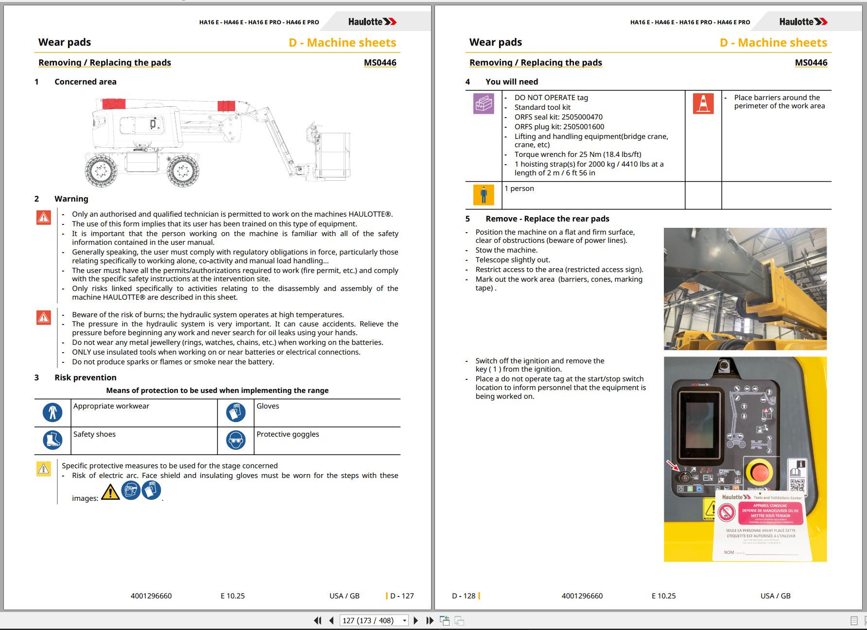
Ms0446 – Removing / Replacing The Pads
1 Concerned Area
2 Warning
3 Risk Prevention
4 You Will Need
5 Remove – Replace The Rear Pads
6 Removing – Refitting The Upper Rear Pads
7 Removing And Installing All The Pads At The Rear Of The Telescope
8 Re-Installation
9 Additional Operations
Ms0447 – Remove – Replace The Boom/Jib/Box Assembly
1 Concerned Area
2 Warning
3 Risk Prevention
4 You Will Need
5 Removal
6 Re-Installation
7 Additional Operations
Ms0448 – Remove – Replace Arm Assembly
1 Concerned Area
2 Warning
3 Risk Prevention
4 You Will Need
5 Removal
6 Re-Installation
7 Additional Operations
Ms0449 – Removal – Replacement Of The Drive Controller + Equipment Pump
1 Concerned Area
2 Warning
3 Risk Prevention
4 You Will Need
5 Removal
6 Re-Installation
7 Additional Operations
Ms0450 – Remove/Re-Install The Harness Can Bus
1 Concerned Area
2 Warning
3 Risk Prevention
4 You Will Need
5 Removal
6 Re-Installation
7 Additional Operations
Ms0451 – Removal – Reinstallation Of The Chargers
1 Concerned Area
2 Warning
3 Risk Prevention
4 You Will Need
5 Removal - General Points
6 Removal - Standard Charger
7 Removal: Optional Charger (If The Machine Is Equipped With The Fast Charge Option With Range Extender)
8 Re-Installation
Ms0452 – Removal – Reinstallation Of The Electric Pump Or Electric Drive Motor Alone Or Pump Alone
1 Concerned Area
2 Warning
3 Risk Prevention
4 You Will Need
5 Refit The Motor Pump Unit
6 Removing The Electric Motor Without Draining
7 Removing The Hydraulic Pump
8 Re-Installation
9 Additional Operations
Ms0453 – Dismantling/Reassembling The Tilt Sensor
1 Concerned Area
2 Warning
3 Risk Prevention
4 You Will Need
5 Information
6 Dis-Assembly
7 Reassembly
8 Additional Operations
Ms0454 – Placing The Machine In Maintenance Configuration
1 Concerned Area
2 Warning
3 Risk Prevention
4 You Will Need
5 Placing The Machine In Maintenance Configuration
6 Putting In Use Position
Ms0455 – Removal – Replacement Of Semi-Traction Batteries
1 Concerned Area
2 Warning
3 Risk Prevention
4 You Will Need
5 Removal
6 Re-Installation
Ms0456 – Removal – Replacement Of Battery Compartments
1 Concerned Area
2 Warning
3 Risk Prevention
4 You Will Need
5 Removal
6 Re-Installation
7 Additional Operations
Ms0457 – Removal – Replacement Of The Bms (Battery Monitoring Sensor)
1 Concerned Area
2 Warning
3 Risk Prevention
4 You Will Need
5 Removal
6 Re-Installation
Ms0458 – Removal – Reinstallation Of The Oscillating Axle Locking Cylinder
1 Concerned Machines
2 Concerned Area
3 Warning
4 Risk Prevention
5 You Will Need
6 Removal
7 Re-Installation
8 Additional Operations
Ms0459 – Removal – Replacement Of Electric Drive Motor
1 Concerned Area
2 Warning
3 Risk Prevention
4 You Will Need
5 Removal
6 Re-Installation
7 Additional Operations
Ms0460 – Remove – Reinstall The Drive Shaft
1 Concerned Area
2 Warning
3 Risk Prevention
4 You Will Need
5 Removal
6 Re-Installation
Ms0461 – Remove – Reinstall The Axle Assembly
1 Concerned Area
2 Warning
3 Risk Prevention
4 You Will Need
5 Removal
6 Re-Installation
7 Additional Operations
Ms0503 – Removal – Refitting Of The Weighing System Force Sensor
1 Concerned Area
2 Warning
3 Risk Prevention
4 You Will Need
5 Removal
6 Re-Installation
7 Additional Operations
Trouble Shooting
1 Trouble Shooting
1.1 Recommendations
1.2 Description
1.3 Requirements
1.4 Failures List
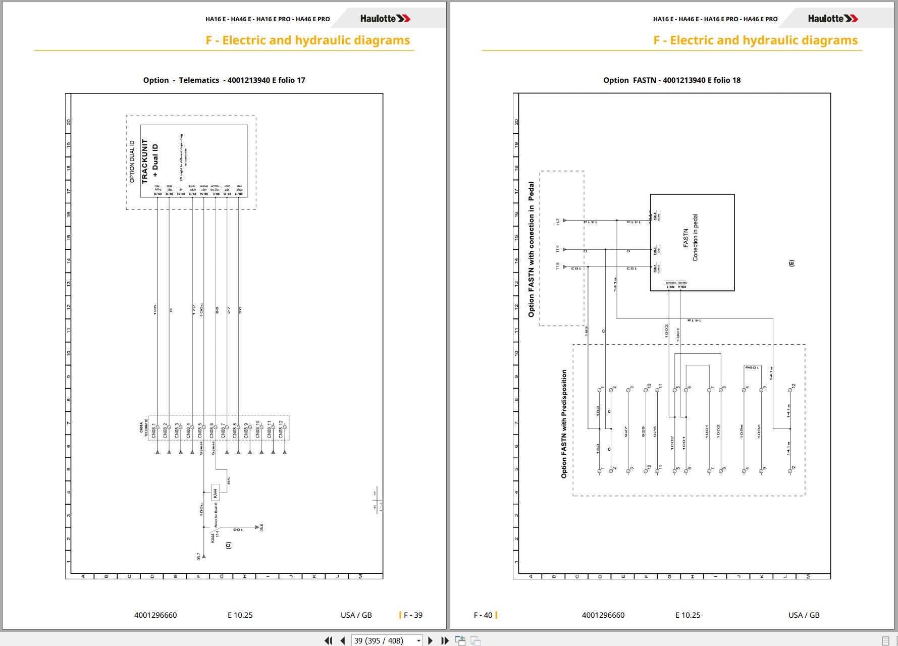
Electric And Hydraulic Diagrams
1 Wiring Diagram
1.1 Electric Diagram - Ha16 E – Ha46 E – Ha16 E Pro – Ha46 E Pro
1.2 Electric Diagram - Ha16 E Pro 360 – Ha46 E Pro 360
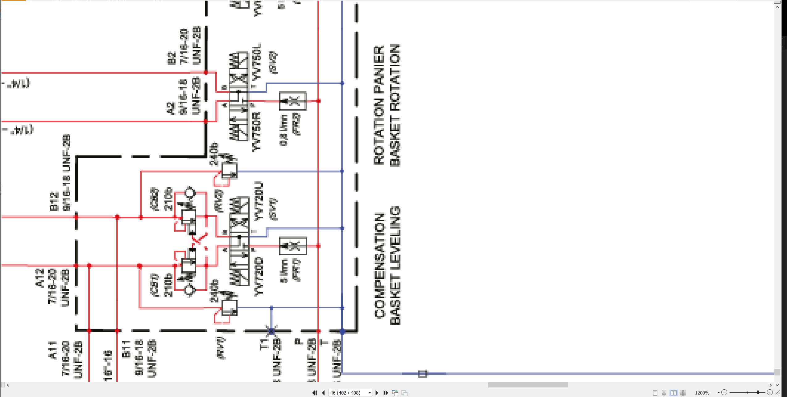
2 Hydraulic Diagram
2.1 Hydraulic Diagram
Records
1 Intervention Register
Related Products
-
Haulotte Work Platforms PDF 23.45 GB Updated [08.2021] Service, Maintenance & Operators Manual, Training & Spare Parts Manual DVD
Original price was: 600.340Current price is: 340. USDHaulotte Work Platforms PDF 23.45 GB Updated [08.2021] Service, Maintenance & Operators Manual, Training & Spare Parts Manual DVDSize: 23.45 GBLanguage: EnglishType: Haulotte Work Platforms and Telehandlers Service, Maintenance & Operators Manual, Training & Spare Parts Manual DVDType of Machine: Haulotte Work PlatformsFormat: PDFWindows: Window 7, Window 8, Window 10 32 & 64 BitAmount of DVD: 5 DVDDVD 1 Untill 2020DVD 2 2020-06.2020DVD 3 06.2020-23.09.2020DVD 4 09.2020-16.05.2021DVD 5 16.05.2021-06.08.2021 (2,25GB)Hot-43%
REALEASE :
11.08.2021
REALEASE :
11.08.2021
-
Liebherr Mining Excavators 76.3Gb PDF Updated 10.2021 Service Manuals DVD
USDLiebherr Mining Excavators 76.3Gb PDF Updated 10.2021 Service Manuals DVDSize: 76.3 Gb (PDF Files)Language: EnglishBrand: LiebherrFormat: PDFType of vehicle: Mining ExcavatorsType of manual: Service ManualUpdate: 10.2021OS: All WindowsAmount of DVD: 1 DVDNOTE: CONTACT TO EMAIL “admin@autoepcservice.com or autoepcservice@gmail.com” FOR PRICEREALEASE :
10.21.2021
-
Liebherr Mining Excavator 15.07GB PDF Updated 10.2021 Operating Manual DVD
USDLiebherr Mining Excavator 15.07GB PDF Updated 10.2021 Operating Manual DVDSize: 15.07 Gb (PDF Files)Language: ENFormat: PDFBrand: LiebherrType of manuals: Operating ManualsType of vehicle: Mining VehicleDate Update: 10.2021OS: All WindowsQuantity of CD: 1 DVDHigh-Speed link DownloadREALEASE :
10.21.2021
-
Haulotte Work Platforms [10.2020] Service, Maintenance & Operators Manual, Training & Spare Parts Manual DVD
Original price was: 400.260Current price is: 260. USDHaulotte Work Platforms [10.2020] Service, Maintenance & Operators Manual, Training & Spare Parts Manual DVD Size: 19 Gb Language: English Type: Haulotte Work Platforms and Telehandlers Service, Maintenance & Operators Manual, Training & Spare Parts Manual Type of Machine: Haulotte Work Platforms Format: PDF Windows: Window 7, Window 8, Window 10 32 & 64 Bit Amount of DVD: 3 DVD 1 DVD Untill 2020 1 DVD 2020-06.2020 1 DVD 06.2020-23.09.2020 High Speed Link DownloadHot-35%
REALEASE :
07.10.2020
REALEASE :
07.10.2020
-
Haulotte Work Platforms PDF 21,2GB Updated [06.2021] Service, Maintenance & Operators Manual, Training & Spare Parts Manual DVD
Original price was: 500.240Current price is: 240. USDHaulotte Work Platforms PDF 21,2GB Updated [06.2021] Service, Maintenance & Operators Manual, Training & Spare Parts Manual DVD Size: 21,2GB Language: English Type: Haulotte Work Platforms and Telehandlers Service, Maintenance & Operators Manual, Training & Spare Parts Manual DVD Type of Machine: Haulotte Work Platforms Format: PDF Windows: Window 7, Window 8, Window 10 32 & 64 Bit Amount of DVD: 4 DVD DVD 1 Untill 2020 DVD 2 2020-06.2020 DVD 3 06.2020-23.09.2020 DVD 4 09.2020-16.05.2021 High Speed Link DownloadHot-52%
REALEASE :
29.05.2021
REALEASE :
29.05.2021
-
Haulotte Service Manual Library PDF 4.10 GB
Original price was: 300.120Current price is: 120. USDThis is a service information package, you will need to use this to repair a vehicleHot-60%
REALEASE :
REALEASE :
-
Haulotte Work Platforms PDF 7.27 GB Updated 2022 Service, Maintenance & Operators Manual & Spare Parts Manual DVD 02
Original price was: 200.140Current price is: 140. USDHaulotte Work Platforms PDF 7.27 GB Updated 2022 Service, Maintenance & Operators Manual & Spare Parts Manual DVD 02Size: 7.27 GBLanguage: EnglishType of document:Haulotte Work Platforms and Telehandlers Maintenance manualHaulotte Work Platforms and Telehandlers Operators manualHaulotte Work Platforms and Telehandlers Service ManualHaulotte Work Platforms and Telehandlers Spare Parts manualType of Machine: Haulotte Work PlatformsFormat: PDFWindows: Window 7, Window 8, Window 10, Window 11 32 & 64 BitAmount of DVD: 1 DVD_02Hot-30%
REALEASE :
05.04.2022
REALEASE :
05.04.2022
-
Haulotte Operating Maintenance Repair Parts Service Manuals PDF 7.03GB Collection
Original price was: 300.120Current price is: 120. USDThis is a service information package, you will need to use this to repair a vehicleHot-60%
REALEASE :
REALEASE :

