
0 ITEMSVIEW CART

✓
Expert Support
✓
Full Speed
✓
100% Working
Haulotte Articulating Boom Lift HA16RTJ to HA16RTJPRO Service Repair Manual 4001317360 06.2025 EN
Size: 60.05 MB
Format: PDF
Language: English
Brand: Haulotte
Type of Machine: Articulating Boom Lift
Type of Manual: Service Manual, Repair Manual, Wiring Diagram, Hydraulic Diagram
Model: Haulotte HA16RTJ, HA46RTJ, HA16RTJO, HA46RTJO, HA16RTJPRO Color Screen Display Articulating Boom Lift
Part Number: 4001317360
Publication Date: 06.2025
Number of Pages: 400 Pages
50 USD
- Description
Description
Contents:
Responsibilities And Commitments
1 Foreword
2 Responsibilities
2.1 Owner’s Responsibility
2.2 Technician’s Responsability
3 Haulotte Commitments
3.1 Haulotte Services
3.2 Training
3.3 Product Information
4 Conditions Of Warranty
Safety
1 General Safety Rules
1.1 Uncontrolled Movement Hazard
1.2 Electric Shock Hazards
1.3 Explosion / Fire Hazards
2 Safety Rules Energy Source Motorization
2.1 General Safety And Specific Interventions On The Thermal Engine
Familiarization
1 Haulotte Activ’screen 2
2 List Of Actuators And Sensors
2.1 Sensors And Actuators
3 Consumables (Oils - Fuels - Engine Oil - Coolant Level…)
3.1 Fuel
3.2 Engine Oil
3.3 Hydraulic Oil
3.4 Gear Motor Oil
3.5 Coolant
3.6 Cylinder Storage Oil
3.7 Grease
3.8 Marine Protection
3.9 Consumables
4 Movement Speed
Machine Sheets
Machine Sheets
Ms0001 – Structural Part Inspection
1 Warning
2 Risk Prevention
3 You Will Need
4 Control And Maintenance
Ms0002 – Pins And Bearing Inspection
1 Warning
2 Risk Prevention
3 You Will Need
4 Control And Maintenance
5 Criteria Of Replacement
6 Procedure Of Reassembly
Ms0003 – Cylinder Inspection
1 Warning
2 Risk Prevention
3 You Will Need
4 Control And Maintenance
Ms0004 – Braking Test Procedure
1 Warning
2 Risk Prevention
3 You Will Need
4 Test Procedure
Ms0005 – Torque Values
1 Metric Torque Chart
2 Sae Fastener Torque Chart
3 Hydraulic Couplings And Hoses Tightening Torque Charts
4 Ha16rtj – Ha16rtjo – Ha16rtj Pro – Ha46rtjo – Ha46rtj Pro
Ms0008 – Oscillating Axles - Functional Tests
1 Warning
2 Risk Prevention
3 You Will Need
4 Oscillating Axles
Ms0009 – Fuel Tank - Filling-Up
1 Warning
2 Risk Prevention
3 You Will Need
4 Consumable
5 Filling
Ms0010 – Slew Ring Inspection
1 You Will Need
2 Preliminary Operation
3 Lubrication
4 Tightening
5 Slew Ring Inspection
Ms0019 – Hydraulic Oil-Level Replacement
1 You Will Need
2 Preliminary Operation
3 Level Control
4 Replacement Of Hydraulic Oil
Ms0020 – Hoses Inspection - Replacement
1 You Will Need
2 Control And Inspections
3 Hoses Disassembling
4 Hoses Reassembly
Ms0021 – Hydraulic Filter Cartridge Replacement
1 You Will Need
2 Hydraulic Filter Cartridge Replacement
Ms0029a – Kubota Diesel Engine
1 Product Information
2 Localization Identification Plate
3 Names Of Parts
4 Operating The Engine
5 Maintenance
6 Periodic Service
7 Carriage And Storage
8 Troubleshooting
Ms0029c – Perkins Diesel Engine
1 Localization Identification Plate
2 Safety Precautions
3 Technical Specifications
4 Names Of Parts
5 Operating The Engine
6 Maintenance
7 Fuel
8 Oil
9 Anti-Freeze
10 Carriage And Storage
11 Troubleshooting
Ms0029f – Kohler Diesel Engine
1 Localization Identification Plate
2 Technical Specifications
3 Names Of Parts
4 Operating The Engine
5 Maintenance
6 Fuel
7 Oil
8 Anti-Freeze
9 Carriage And Storage
10 Troubleshooting
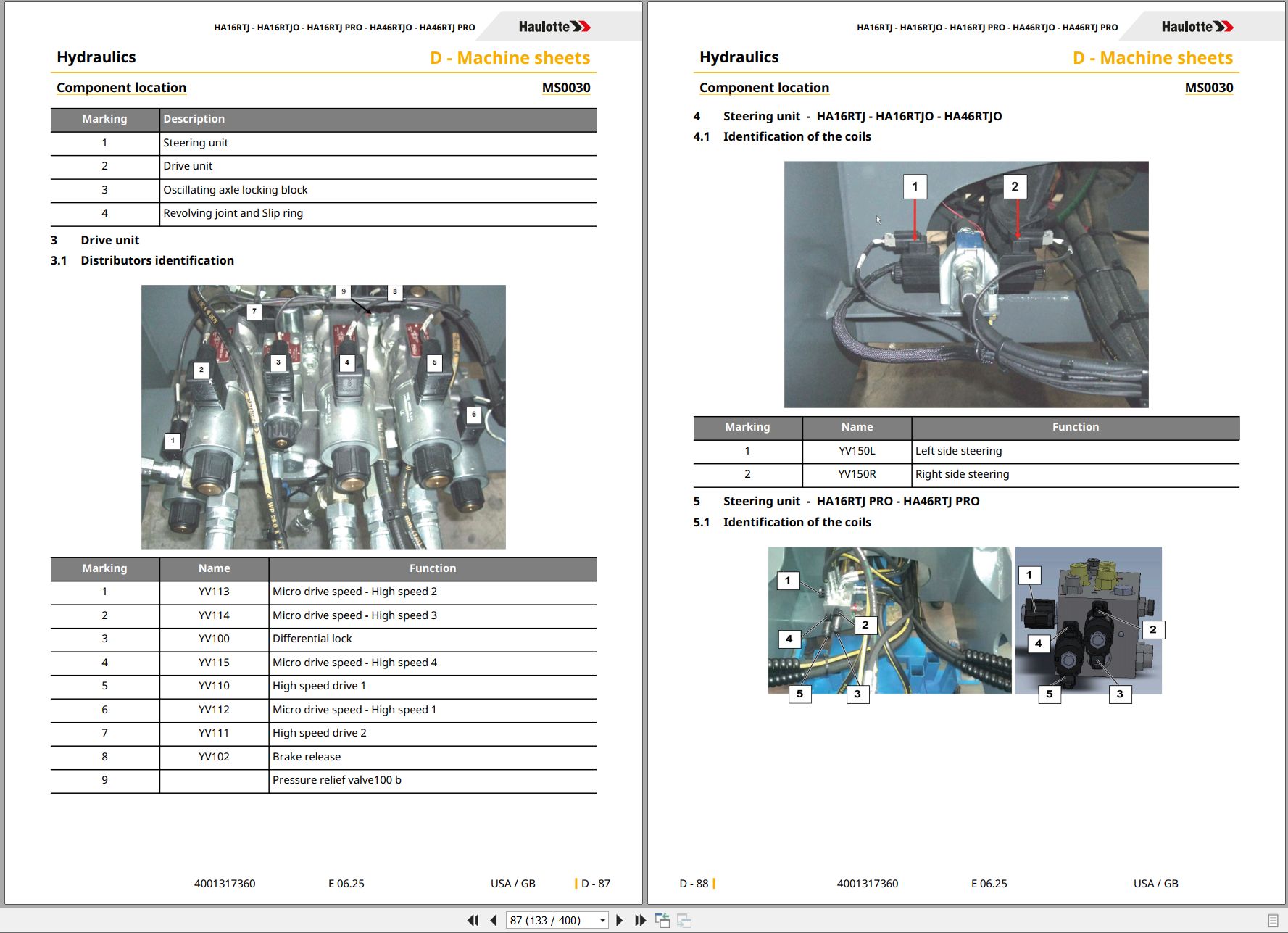
Ms0030 – Component Location
1 You Will Need
2 Localization Of Hydraulic Blocks In The Chassis
3 Drive Unit
4 Steering Unit - Ha16rtj – Ha16rtjo – Ha46rtjo
5 Steering Unit - Ha16rtj Pro – Ha46rtj Pro
6 Oscillating Axle Locking Block - Ha16rtj O / Pro – Ha46rtj O / Pro
7 Location Of The Turntable Components
8 Unit Pvg
9 Ground Control Box And Spu
10 Pcb Inside The Ground Control Box
11 Spu7066
12 Engine
13 Hydraulic Pump
14 Recapitulation Of Pressures
15 Position Of Ils Sensors, Arm, Boom And Telescop
16 Hydraulic Block On/Off
17 Load Cell
18 Platform Control Box
Ms0031 – Overload System
1 You Will Need
2 Level Of Knowledge Required
3 Safety Instructions
4 Periodic Inspection
5 Calibration Procedure
6 Checks
Ms0032 – Tires (Tyres) And Pressures-Wheel Replacement
1 You Will Need
2 Preliminary Operation
3 Technical Specifications
4 Wheel And Tires/Tyres Inspections
5 Wheel Replacement
Ms0034 – Dismantling / Reassembling Wheels Reducer
1 You Will Need
2 Level Of Knowledge Required
3 Safety Instructions
4 Removal
5 Reinstall
6 Additional Operations
Ms0035 – Check And Replacing The Pads
1 You Will Need
2 Level Of Knowledge Required
3 Safety Instructions
4 Removal/Reinstall-Rear Pads
Ms0036 – Telescopic Cylinder Replacement
1 You Will Need
2 Level Of Knowledge Required
3 Safety Instructions
4 Removal
5 Reinstall
6 Additional Operations
Ms0038 – Pressure Adjustment
1 You Will Need
2 Pressure Adjustment
3 Pressure Plug Location
Ms0109 – Draining The Wheel Reducer
1 You Will Need
2 Level Of Knowledge Required
3 Safety Instructions
4 Additional Operations
Ms0133 – Universal Plug
1 You Will Need
2 Procedure
Ms0165 – Remove/Re-Install Output Compensation Cylinder
1 Warning
2 Risk Prevention
3 You Will Need
4 Removal
5 Re-Installation
6 Additional Operations
Ms0166 – Remove – Replace Load Cell
1 Warning
2 Risk Prevention
3 You Will Need
4 Removal
5 Re-Installation
6 Additional Operations
Ms0167 – Remove – Replace Boom Cylinder
1 Warning
2 Risk Prevention
3 You Will Need
4 Removal
5 Re-Installation
6 Additional Operations
Ms0168 – Remove – Replace Arm Cylinder
1 Warning
2 You Will Need
3 Preliminary Operation
4 Removal
5 Re-Installation
6 Additional Operations
Ms0169 – Remove/Re-Install Input Compensation Cylinder
1 Warning
2 You Will Need
3 Preliminary Operation
4 Removal
5 Re-Installation
6 Additional Operations
Ms0170 – Removal – Replacement Of The Platform
1 Warning
2 You Will Need
3 Preliminary Operation
4 Removal
5 Re-Installation
6 Additional Operations
Ms0171 – Remove – Replace Arm Assembly
1 Warning
2 You Will Need
3 Preliminary Operation
4 Removal
5 Re-Installation
6 Additional Operations
Ms0172 – Remove – Replace Boom Assembly
1 Warning
2 You Will Need
3 Preliminary Operation
4 Removal
5 Re-Installation
6 Additional Operations
Ms0180 – Battery (Ies)
1 You Will Need
2 Technical Specifications
3 Starter Battery Inspection
Ms0237 – Remove – Replace Counterweight
1 Warning
2 You Will Need
3 Preliminary Operation
4  Ha16rtjpro/Ha16rtjo Counterweight General Arrangement Plan
5  Ha16rtj Counterweight General Arrangement Plan
6 Removal
7 Re-Installation
8 Additional Operations
Ms0285 – Maintenance Implementation
1 Placing In Configuration
Ms0396 – Overload System - Instrumented Axis
1 Concerned Machines
2 Level Of Knowledge Required
3 Safety Instructions
4 You Will Need
5 Location Of The Load Pin Sensor
6 When Should You Make A Calibration
7 Configuring The Machine Before Start Calibration
8 Procedure
9 Offset Of Load Management System With Platform Empty
10 Gain Of Load Management System With Fixed Weight
11 Gain Of Load Management System With Adjustable Weight
12 Fault Codes Linked To The Overload System
13 Checks
Ms0503 – Removal – Refitting Of The Weighing System Force Sensor
1 Concerned Area
2 Warning
3 Risk Prevention
4 You Will Need
5 Removal
6 Re-Installation
7 Additional Operations
Trouble Shooting
1 Trouble Shooting
1.1 Recommendations
1.2 Description
1.3 Requirements
1.4 Failures List
2 Legend
2.1 Pcb Turret
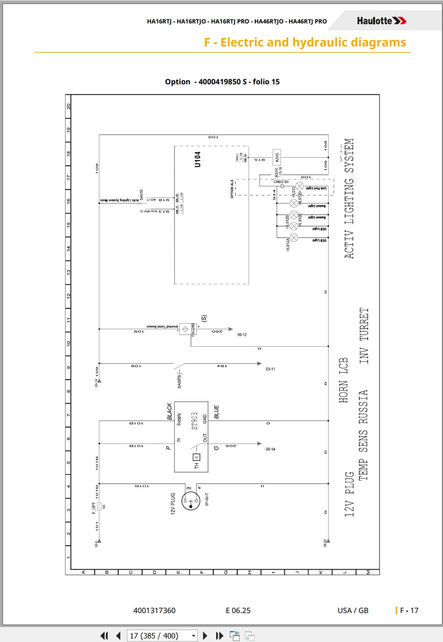
Electric And Hydraulic Diagrams
1 Wiring Diagram
1.1 Electric Diagram
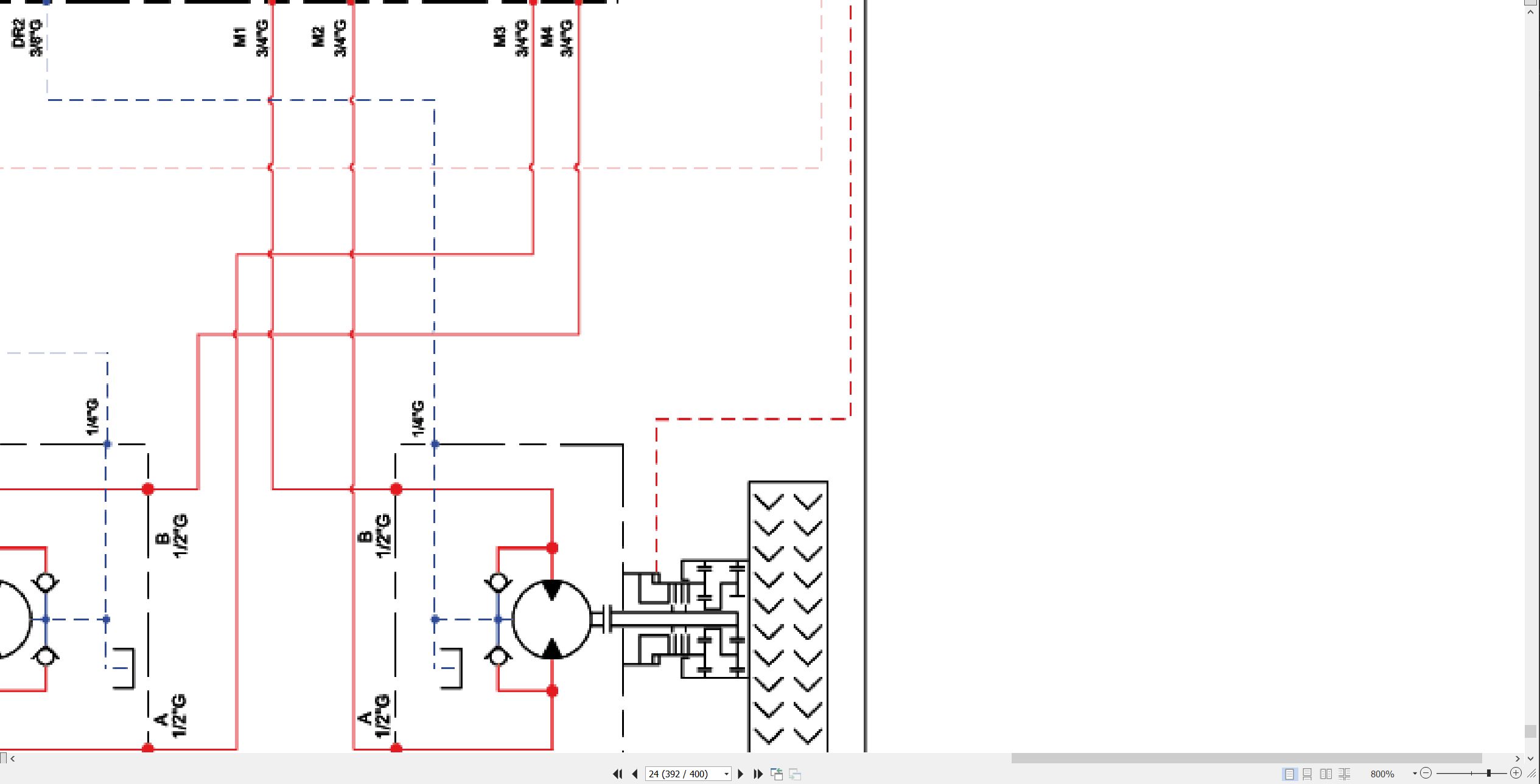
2 Hydraulic Diagram
2.1 Hydraulic Diagram
Records
1 Intervention Register
Related Products
-
Haulotte Operating Maintenance Repair Parts Service Manuals PDF 7.03GB Collection
Original price was: 300.120Current price is: 120. USDThis is a service information package, you will need to use this to repair a vehicleHot-60%
REALEASE :
REALEASE :
-
Haulotte Work Platforms PDF 7.27 GB Updated 2022 Service, Maintenance & Operators Manual & Spare Parts Manual DVD 02
Original price was: 200.140Current price is: 140. USDHaulotte Work Platforms PDF 7.27 GB Updated 2022 Service, Maintenance & Operators Manual & Spare Parts Manual DVD 02Size: 7.27 GBLanguage: EnglishType of document:Haulotte Work Platforms and Telehandlers Maintenance manualHaulotte Work Platforms and Telehandlers Operators manualHaulotte Work Platforms and Telehandlers Service ManualHaulotte Work Platforms and Telehandlers Spare Parts manualType of Machine: Haulotte Work PlatformsFormat: PDFWindows: Window 7, Window 8, Window 10, Window 11 32 & 64 BitAmount of DVD: 1 DVD_02Hot-30%
REALEASE :
05.04.2022
REALEASE :
05.04.2022
-
Liebherr Mining Excavator 15.07GB PDF Updated 10.2021 Operating Manual DVD
USDLiebherr Mining Excavator 15.07GB PDF Updated 10.2021 Operating Manual DVDSize: 15.07 Gb (PDF Files)Language: ENFormat: PDFBrand: LiebherrType of manuals: Operating ManualsType of vehicle: Mining VehicleDate Update: 10.2021OS: All WindowsQuantity of CD: 1 DVDHigh-Speed link DownloadREALEASE :
10.21.2021
-
Haulotte Service Manual Library PDF 4.10 GB
Original price was: 300.120Current price is: 120. USDThis is a service information package, you will need to use this to repair a vehicleHot-60%
REALEASE :
REALEASE :
-
Haulotte Work Platforms [10.2020] Service, Maintenance & Operators Manual, Training & Spare Parts Manual DVD
Original price was: 400.260Current price is: 260. USDHaulotte Work Platforms [10.2020] Service, Maintenance & Operators Manual, Training & Spare Parts Manual DVD Size: 19 Gb Language: English Type: Haulotte Work Platforms and Telehandlers Service, Maintenance & Operators Manual, Training & Spare Parts Manual Type of Machine: Haulotte Work Platforms Format: PDF Windows: Window 7, Window 8, Window 10 32 & 64 Bit Amount of DVD: 3 DVD 1 DVD Untill 2020 1 DVD 2020-06.2020 1 DVD 06.2020-23.09.2020 High Speed Link DownloadHot-35%
REALEASE :
07.10.2020
REALEASE :
07.10.2020
-
Haulotte Work Platforms PDF 21,2GB Updated [06.2021] Service, Maintenance & Operators Manual, Training & Spare Parts Manual DVD
Original price was: 500.240Current price is: 240. USDHaulotte Work Platforms PDF 21,2GB Updated [06.2021] Service, Maintenance & Operators Manual, Training & Spare Parts Manual DVD Size: 21,2GB Language: English Type: Haulotte Work Platforms and Telehandlers Service, Maintenance & Operators Manual, Training & Spare Parts Manual DVD Type of Machine: Haulotte Work Platforms Format: PDF Windows: Window 7, Window 8, Window 10 32 & 64 Bit Amount of DVD: 4 DVD DVD 1 Untill 2020 DVD 2 2020-06.2020 DVD 3 06.2020-23.09.2020 DVD 4 09.2020-16.05.2021 High Speed Link DownloadHot-52%
REALEASE :
29.05.2021
REALEASE :
29.05.2021
-
Haulotte Work Platforms PDF 23.45 GB Updated [08.2021] Service, Maintenance & Operators Manual, Training & Spare Parts Manual DVD
Original price was: 600.340Current price is: 340. USDHaulotte Work Platforms PDF 23.45 GB Updated [08.2021] Service, Maintenance & Operators Manual, Training & Spare Parts Manual DVDSize: 23.45 GBLanguage: EnglishType: Haulotte Work Platforms and Telehandlers Service, Maintenance & Operators Manual, Training & Spare Parts Manual DVDType of Machine: Haulotte Work PlatformsFormat: PDFWindows: Window 7, Window 8, Window 10 32 & 64 BitAmount of DVD: 5 DVDDVD 1 Untill 2020DVD 2 2020-06.2020DVD 3 06.2020-23.09.2020DVD 4 09.2020-16.05.2021DVD 5 16.05.2021-06.08.2021 (2,25GB)Hot-43%
REALEASE :
11.08.2021
REALEASE :
11.08.2021
-
Liebherr Mining Excavators 76.3Gb PDF Updated 10.2021 Service Manuals DVD
USDLiebherr Mining Excavators 76.3Gb PDF Updated 10.2021 Service Manuals DVDSize: 76.3 Gb (PDF Files)Language: EnglishBrand: LiebherrFormat: PDFType of vehicle: Mining ExcavatorsType of manual: Service ManualUpdate: 10.2021OS: All WindowsAmount of DVD: 1 DVDNOTE: CONTACT TO EMAIL “admin@autoepcservice.com or autoepcservice@gmail.com” FOR PRICEREALEASE :
10.21.2021

