
0 ITEMSVIEW CART

✓
Expert Support
✓
Full Speed
✓
100% Working
Haulotte Articulating Boom Lift HA20LE to HA61LE PRO Service Repair Manual 4001303950 07.2025 EN
Size: 72.47 MB
Format: PDF
Language: English
Brand: Haulotte
Type of Machine: Articulating Boom Lift
Type of Manual: Service Manual, Repair Manual, Wiring Diagram, Hydraulic Diagram
Model: Haulotte HA20LE, HA61LE, HA20LE PRO, HA61LE PRO Touch Screen Display Articulating Boom Lift
Part Number: 4001303950
Publication Date: 07.2025
Number of Pages: 508 Pages
30 USD
- Description
Description
Contents:
Responsibilities and commitments
1 Foreword
2 Responsibilities
2.1 Owner’s responsibility
2.2 Technician’s responsability
3 HAULOTTE® commitments
3.1 HAULOTTE Services®
3.2 Training
3.3 Product information
4 Conditions of warranty
Safety
1 General safety rules
1.1 Uncontrolled movement Hazard
1.2 Electric Shock Hazards
1.3 Explosion / Fire Hazards
2 Safety rules energy source motorization
2.1 General safety and specific interventions on the thermal engine
2.2 General safety and specific interventions on energy storage
Familiarization
1 Touch screen display
2 List of actuators and sensors
2.1 Sensors and actuators
3 Consumables (Oils - Fuels - Engine oil - Coolant level…)
3.1 Fuel
3.2 Engine oil
3.3 Hydraulic oil
3.4 Gear motor oil
3.5 Coolant
3.6 Cylinder storage oil
3.7 Grease
3.8 Marine protection
3.9 Consumables
4 Movement speed
Machine sheets
Machine sheets
MS0001 – Structural part inspection
1 Warning
2 Risk prevention
3 You will need
4 Control and maintenance
MS0002 – Pins and bearing inspection
1 Warning
2 Risk prevention
3 You will need
4 Control and maintenance
5 Criteria of replacement
6 Procedure of reassembly
MS0003 – Cylinder inspection
1 Warning
2 Risk prevention
3 You will need
4 Control and maintenance
MS0004 – Braking test procedure
1 Warning
2 Risk prevention
3 You will need
4 Test procedure
MS0008 – Oscillating axles - Functional tests
1 Warning
2 Risk prevention
3 You will need
4 Oscillating axles
MS0009 – Fuel tank - Filling-up
1 Warning
2 Risk prevention
3 You will need
4 Consumable
5 Filling
MS0031 – Overload system
1 You will need
2 Level of knowledge required
3 Safety instructions
4 Periodic inspection
5 Calibration procedure
6 Checks
MS0133 – Universal plug
1 You will need
2 Procedure
MS0163 – Lock-out procedure
1 Concerned area
2 Warning
3 Risk prevention
4 You will need
5 Procedure
6 Unlocking procedure
MS0181 – Remove – Replace telescope cylinder
1 Concerned area
2 Warning
3 Risk prevention
4 You will need
5 Removal
6 Re-installation
7 Additional operations
MS0182 – Remove/Re-install output compensation cylinder
1 Concerned area
2 Warning
3 Risk prevention
4 You will need
5 Removal
6 Re-installation
7 Additional operations
MS0183 – Removal – Replacement of starter battery
1 Concerned area
2 Warning
3 Risk prevention
4 You will need
5 Removal
6 Re-installation
MS0185 – Removal – Replacement of battery compartments
1 Concerned area
2 Warning
3 Risk prevention
4 You will need
5 Removal
6 Re-installation
7 Additional operations
MS0186 – Removal – Replacement of semi-traction batteries
1 Concerned area
2 Warning
3 Risk prevention
4 You will need
5 Removal
6 Re-installation
7 Additional operations
MS0187 – Removal – Replacement of the BMS (Battery monitoring Sensor)
1 Concerned area
2 Warning
3 Risk prevention
4 You will need
5 Removal
6 Re-installation
7 Additional operations
MS0188 – Removal – Replacement of on-board charger
1 Concerned area
2 Warning
3 Risk prevention
4 You will need
5 Removal
6 Re-installation
7 Additional operations
MS0189 – Removal – Replacement fuses in the power box
1 Concerned area
2 Warning
3 Risk prevention
4 You will need
5 Removal
6 Re-installation
7 Additional operations
MS0190 – Removal – Replacement of CAN insulator in the chassis
1 Concerned area
2 Warning
3 Risk prevention
4 You will need
5 Removal
6 Re-installation
7 Additional operations
MS0191 – Removal – Replacement charger category 1 screen
1 Concerned area
2 Warning
3 Risk prevention
4 You will need
5 Removal
6 Re-installation
7 Additional operations
MS0192 – Removal – Replacement of the drive controller
1 Concerned area
2 Warning
3 Risk prevention
4 You will need
5 Removal
6 Re-installation
7 Additional operations
MS0193 – Removal – Replacement of the electric brake on the gear motor
1 Concerned area
2 Warning
3 Risk prevention
4 You will need
5 Removal
6 Re-installation
7 Additional operations
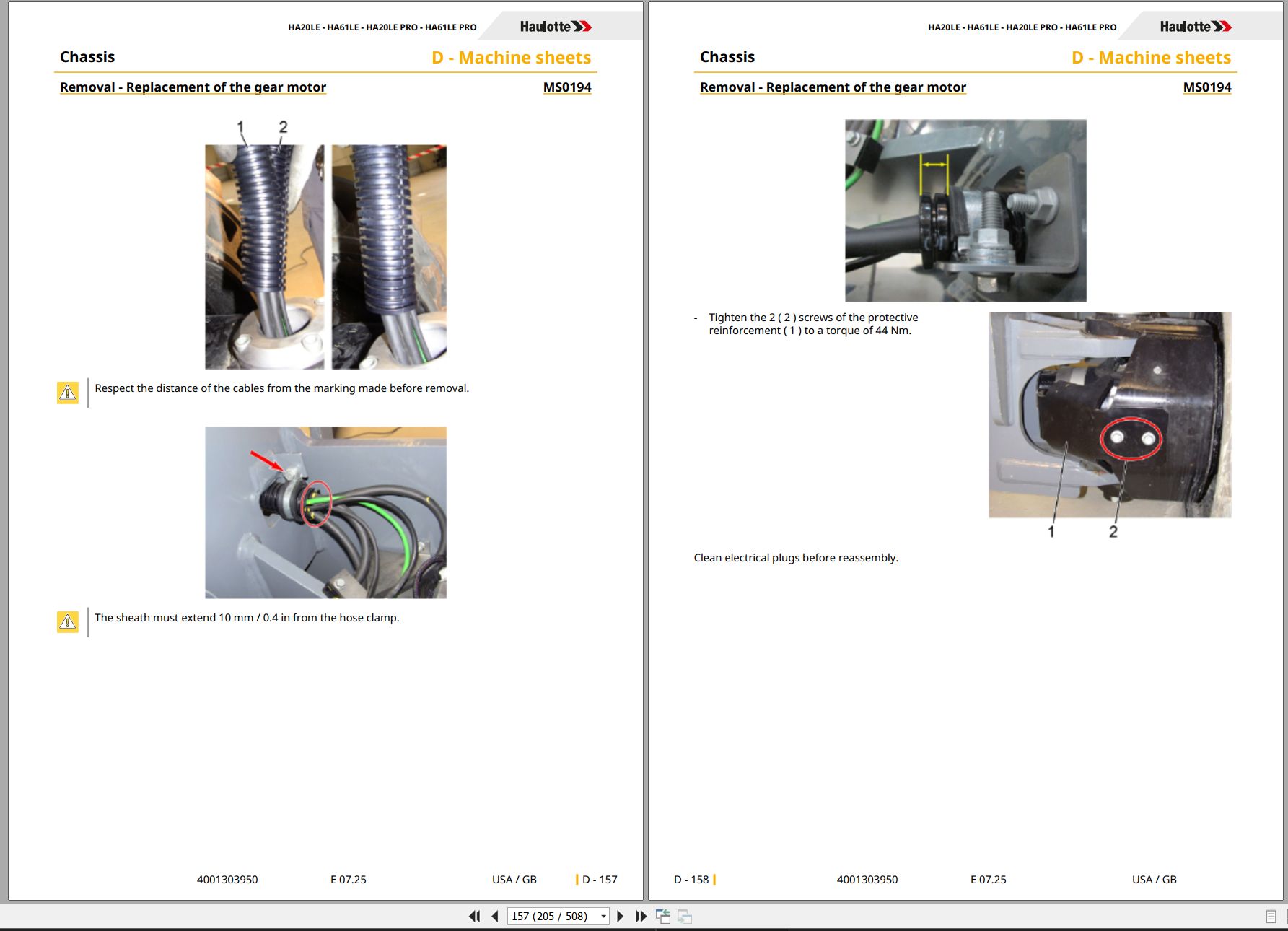
MS0194 – Removal – Replacement of the gear motor
1 Concerned area
2 Warning
3 Risk prevention
4 You will need
5 Removal
6 Re-installation
7 Additional operations
MS0195 – Removal – Replacement of electric drive motor
1 Concerned area
2 Warning
3 Risk prevention
4 You will need
5 Removal
6 Re-installation
7 Additional operations
MS0196 – Remove/replace covers
1 Concerned area
2 Warning
3 Risk prevention
4 You will need
5 Removal
6 Re-installation
7 Additional operations
MS0197 – Removal – Replacement of category 2 screen
1 Concerned area
2 Warning
3 Risk prevention
4 You will need
5 Removal
6 Re-installation
MS0198 – Removal – Replacement of CAN insulator in the turntable
1 Concerned area
2 Warning
3 Risk prevention
4 You will need
5 Removal
6 Re-installation
MS0199 – Removal – Replacement on the generator
1 Concerned area
2 Warning
3 Risk prevention
4 You will need
5 Removal
6 Re-installation
7 Additional operations
MS0200 – Removal – Replacement of the generator variable speed drive
1 Concerned area
2 Warning
3 Risk prevention
4 You will need
5 Removal
6 Re-installation
7 Additional operations
MS0201 – Removal – Replacement of the electro-pump unit
1 Concerned area
2 Warning
3 Risk prevention
4 You will need
5 Removal
6 Re-installation
7 Additional operations
MS0202 – Removal – Replacement of the electro-pump unit variable speed drive
1 Concerned area
2 Warning
3 Risk prevention
4 You will need
5 Removal
6 Re-installation
7 Additional operations
MS0203 – Remove/Re-install input compensation cylinder
1 Concerned area
2 Warning
3 Risk prevention
4 You will need
5 Removal
6 Re-installation
7 Additional operations
MS0204 – Remove/Re-install slip ring (electric rotary coupling)
1 Concerned area
2 Warning
3 Risk prevention
4 You will need
5 Removal
6 Re-installation
7 Additional operations
MS0205 – Remove/Re-install jib cylinder
1 Concerned area
2 Warning
3 Risk prevention
4 You will need
5 Removal
6 Re-installation
7 Additional operations
MS0206 – Removal – Replacement of the jib and platform
1 Concerned area
2 Warning
3 Risk prevention
4 You will need
5 Removal
6 Re-installation
7 Additional operations
MS0207 – Remove – Replace load cell
1 Concerned area
2 Warning
3 Risk prevention
4 You will need
5 Removal
6 Re-installation
7 Additional operations
MS0208 – Remove – Replace counterweight
1 Concerned area
2 Warning
3 Risk prevention
4 You will need
5 Removal
6 Re-installation
7 Additional operations
MS0209 – Remove – Replace the boom/jib/box assembly
1 Concerned area
2 Warning
3 Risk prevention
4 You will need
5 Removal
6 Re-installation
7 Additional operations
MS0210 – Remove – Replace arm assembly
1 Concerned area
2 Warning
3 Risk prevention
4 You will need
5 Removal
6 Re-installation
7 Additional operations
MS0211 – Removal – Replacement of the steering cylinder
1 Concerned area
2 Warning
3 Risk prevention
4 You will need
5 Removal
6 Re-installation
7 Additional operations
MS0212 – Removing/re-installing the oscillating axle actuator
1 Concerned area
2 Warning
3 Risk prevention
4 You will need
5 Removal
6 Re-installation
7 Additional operations
MS0213 – Draining the oscillating cylinders
1 Concerned area
2 Warning
3 Risk prevention
4 You will need
5 Draining the oscillating cylinders
MS0214 – Static test - Oscillating axle locking cylinder
1 Concerned area
2 Warning
3 Risk prevention
4 You will need
5 Static test - Oscillating axle locking cylinder
6 Additional operations
MS0215 – Remove/Re-install rotary actuator
1 Concerned area
2 Warning
3 Risk prevention
4 You will need
5 Removal
6 Re-installation
7 Additional operations
MS0216 – Removal – Replacement of the platform
1 Concerned area
2 Warning
3 Risk prevention
4 You will need
5 Removal
6 Re-installation
7 Additional operations
MS0217 – Removal – Replacement of platform – boom BUS CAN harness
1 Concerned area
2 Warning
3 Risk prevention
4 You will need
5 Removal
6 Re-installation
7 Additional operations
MS0218 – Removal – Replacement of boom-turntable BUS CAN harness
1 Concerned area
2 Warning
3 Risk prevention
4 You will need
5 Removal
6 Re-installation
7 Additional operations
MS0219 – Remove – Replace arm cylinder
1 Concerned area
2 Warning
3 Risk prevention
4 You will need
5 Removal
6 Re-installation
7 Additional operations
MS0220 – Removal – Replacement boom cylinder
1 Concerned area
2 Warning
3 Risk prevention
4 You will need
5 Removal
6 Re-installation
7 Additional operations
MS0221 – Removing / Replacing the pads
1 Concerned area
2 Warning
3 Risk prevention
4 You will need
5 Removal
6 Re-installation
7 Additional operations
MS0222 – Draining the rotary cylinder
1 Concerned area
2 Warning
3 Risk prevention
4 You will need
5 Draining the rotary cylinder
MS0223 – Check of tilt sensor
1 Concerned area
2 Warning
3 Risk prevention
4 You will need
5 Check of tilt sensor
MS0285 – Maintenance implementation
1 Placing in configuration
Trouble shooting
1 Trouble shooting
1.1 Recommendations
1.2 Description
1.3 Requirements
1.4 Failures list
2 Legend
2.1 PCBÂ Turret
Electric and hydraulic diagrams
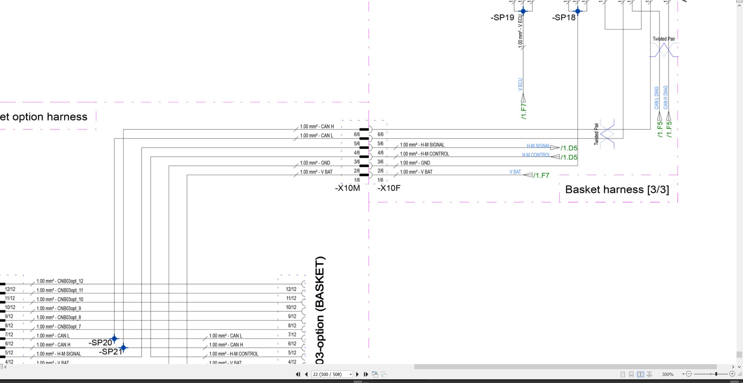
1 Wiring diagram
1.1 Electric diagram
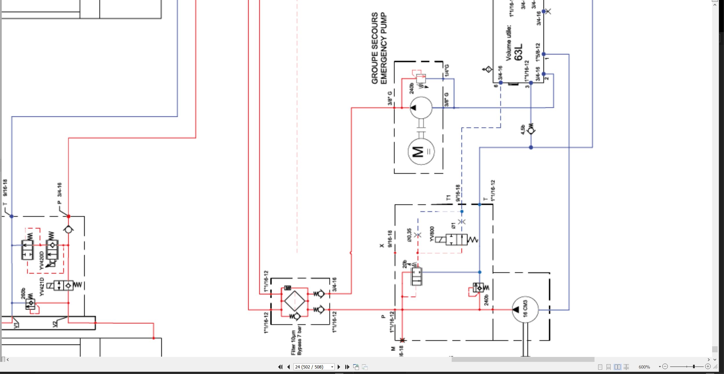
2 Hydraulic diagram
2.1 Hydraulic diagram
Records
1 Intervention register
Related Products
-
Haulotte Service Manual Library PDF 4.10 GB
Original price was: 300.120Current price is: 120. USDThis is a service information package, you will need to use this to repair a vehicleHot-60%
REALEASE :
REALEASE :
-
Haulotte Work Platforms PDF 7.27 GB Updated 2022 Service, Maintenance & Operators Manual & Spare Parts Manual DVD 02
Original price was: 200.140Current price is: 140. USDHaulotte Work Platforms PDF 7.27 GB Updated 2022 Service, Maintenance & Operators Manual & Spare Parts Manual DVD 02Size: 7.27 GBLanguage: EnglishType of document:Haulotte Work Platforms and Telehandlers Maintenance manualHaulotte Work Platforms and Telehandlers Operators manualHaulotte Work Platforms and Telehandlers Service ManualHaulotte Work Platforms and Telehandlers Spare Parts manualType of Machine: Haulotte Work PlatformsFormat: PDFWindows: Window 7, Window 8, Window 10, Window 11 32 & 64 BitAmount of DVD: 1 DVD_02Hot-30%
REALEASE :
05.04.2022
REALEASE :
05.04.2022
-
Haulotte Work Platforms [10.2020] Service, Maintenance & Operators Manual, Training & Spare Parts Manual DVD
Original price was: 400.260Current price is: 260. USDHaulotte Work Platforms [10.2020] Service, Maintenance & Operators Manual, Training & Spare Parts Manual DVD Size: 19 Gb Language: English Type: Haulotte Work Platforms and Telehandlers Service, Maintenance & Operators Manual, Training & Spare Parts Manual Type of Machine: Haulotte Work Platforms Format: PDF Windows: Window 7, Window 8, Window 10 32 & 64 Bit Amount of DVD: 3 DVD 1 DVD Untill 2020 1 DVD 2020-06.2020 1 DVD 06.2020-23.09.2020 High Speed Link DownloadHot-35%
REALEASE :
07.10.2020
REALEASE :
07.10.2020
-
Haulotte Work Platforms PDF 21,2GB Updated [06.2021] Service, Maintenance & Operators Manual, Training & Spare Parts Manual DVD
Original price was: 500.240Current price is: 240. USDHaulotte Work Platforms PDF 21,2GB Updated [06.2021] Service, Maintenance & Operators Manual, Training & Spare Parts Manual DVD Size: 21,2GB Language: English Type: Haulotte Work Platforms and Telehandlers Service, Maintenance & Operators Manual, Training & Spare Parts Manual DVD Type of Machine: Haulotte Work Platforms Format: PDF Windows: Window 7, Window 8, Window 10 32 & 64 Bit Amount of DVD: 4 DVD DVD 1 Untill 2020 DVD 2 2020-06.2020 DVD 3 06.2020-23.09.2020 DVD 4 09.2020-16.05.2021 High Speed Link DownloadHot-52%
REALEASE :
29.05.2021
REALEASE :
29.05.2021
-
Haulotte Work Platforms PDF 23.45 GB Updated [08.2021] Service, Maintenance & Operators Manual, Training & Spare Parts Manual DVD
Original price was: 600.340Current price is: 340. USDHaulotte Work Platforms PDF 23.45 GB Updated [08.2021] Service, Maintenance & Operators Manual, Training & Spare Parts Manual DVDSize: 23.45 GBLanguage: EnglishType: Haulotte Work Platforms and Telehandlers Service, Maintenance & Operators Manual, Training & Spare Parts Manual DVDType of Machine: Haulotte Work PlatformsFormat: PDFWindows: Window 7, Window 8, Window 10 32 & 64 BitAmount of DVD: 5 DVDDVD 1 Untill 2020DVD 2 2020-06.2020DVD 3 06.2020-23.09.2020DVD 4 09.2020-16.05.2021DVD 5 16.05.2021-06.08.2021 (2,25GB)Hot-43%
REALEASE :
11.08.2021
REALEASE :
11.08.2021
-
Liebherr Mining Excavators 76.3Gb PDF Updated 10.2021 Service Manuals DVD
USDLiebherr Mining Excavators 76.3Gb PDF Updated 10.2021 Service Manuals DVDSize: 76.3 Gb (PDF Files)Language: EnglishBrand: LiebherrFormat: PDFType of vehicle: Mining ExcavatorsType of manual: Service ManualUpdate: 10.2021OS: All WindowsAmount of DVD: 1 DVDNOTE: CONTACT TO EMAIL “admin@autoepcservice.com or autoepcservice@gmail.com” FOR PRICEREALEASE :
10.21.2021
-
Liebherr Mining Excavator 15.07GB PDF Updated 10.2021 Operating Manual DVD
USDLiebherr Mining Excavator 15.07GB PDF Updated 10.2021 Operating Manual DVDSize: 15.07 Gb (PDF Files)Language: ENFormat: PDFBrand: LiebherrType of manuals: Operating ManualsType of vehicle: Mining VehicleDate Update: 10.2021OS: All WindowsQuantity of CD: 1 DVDHigh-Speed link DownloadREALEASE :
10.21.2021
-
Haulotte Operating Maintenance Repair Parts Service Manuals PDF 7.03GB Collection
Original price was: 300.120Current price is: 120. USDThis is a service information package, you will need to use this to repair a vehicleHot-60%
REALEASE :
REALEASE :

