
0 ITEMSVIEW CART

✓
Expert Support
✓
Full Speed
✓
100% Working
Haulotte Scissor Lift OPTIMUM 8 OPTIMUM 1931 E Service Repair Manual 4001405210 03.2026 EN
Size: 26.45 MB
Format: PDF
Language: English
Brand: Haulotte
Type of Machine: Scissor Lift
Type of Manual: Service Manual, Repair Manual, Wiring Diagram, Hydraulic Diagram
Model: Haulotte OPTIMUM 8, OPTIMUM 1931 E Color Screen Display Scissor Lift
Part Number: 4001405210
Publication Date: 03.2026
Number of Pages: 246 Pages
50 USD
- Description
Description
Contents:
Responsibilities and commitments
1 Foreword
2 Responsibilities
2.1 Owner’s responsibility
2.1.1 Product modification
2.2 Technician’s responsability
3 HAULOTTE® commitments
3.1 HAULOTTE Services®
3.2 Training
3.3 Product information
3.3.1 Implementing manufacturer safety campaigns
4 Conditions of warranty
Safety
1 General safety rules
1.1 Uncontrolled movement Hazard
1.2 Electric Shock Hazards
1.3 Explosion / Fire Hazards
2 Safety rules energy source motorization
2.1 General safety and specific interventions on energy storage
Familiarization
1 HAULOTTE Activ’Screen
1.1 LCD screen
2 List of actuators and sensors
2.1 Sensors and actuators
3 Consumables (Oils…)
3.1 Hydraulic oil
3.2 Gear motor oil
3.3 Cylinder storage oil
3.4 Grease
3.5 Marine protection
3.6 Consumables
4 Movement speed
Machine sheets
Machine sheets
MS0072 – Pressure adjustment
1 You will need
2 Preliminary operation
3 Pressure adjustment
4 Pressure plug location
MS0073 – Scissor arms screw-Periodical checks
1 You will need
2 Checks
3 Tightening the screws of the scissor arms
MS0084 – Removal / Replacement of motor reducer assembly
1 You will need
2 Preliminary operation
3 Plan of the assembly
4 Removal
5 Reinstall
6 Checks
MS0090 – Removal / replacement of steering pivot assembly
1 You will need
2 Plan of the assembly
3 Removal
4 Reinstall
5 Complementary operations
6 Checks
MS0095 – Removal / replacement of platform assembly
1 You will need
2 Level of knowledge required
3 Preliminary operation
4 Removal
5 Reinstall
6 Complementary operations
7 Checks
MS0096 – Removal / replacement of Scissor pack
1 You will need
2 Preliminary operation
3 Removal
4 Reinstall
5 Complementary operations
6 Checks
MS0097 – Calibration steering
1 You will need
2 Preliminary operation
3 Level of knowledge required
4 Steering calibration procedure
5 Checks
MS0098 – Calibration Load management system
1 You will need
2 Preliminary operation
3 Level of knowledge required
4 Load management calibration Procedure
5 Checks
MS0099 – Calibration arm angle sensors
1 You will need
2 Preliminary operation
3 Level of knowledge required
4 Procedure of load management system calibration
5 Checks
MS0102 – Tires (Tyres)Â -Â Wheel replacement
1 You will need
2 Preliminary operation
3 Technical specifications
4 Wheel and tires/tyres inspections
5 Procedure of replacement
MS0106 – HAULOTTE Activ’Screen
1 You will need
2 Simplified menus
3 Detailed menus
3.1 Screen access code settings
3.1.1 Screen 0d
MS0133 – Universal plug
1 You will need
2 Procedure
MS0174 – Platform extension lock assembly
1 You will need
2 Level of knowledge required
3 Preliminary operation
4 Procedure
5 Additional operations
6 Checks
MS0175 – Removal – Replacement of the motor/pump assembly
1 You will need
2 Level of knowledge required
3 Preliminary operation
4 Removal
5 Reinstall
6 Complementary operations
7 Checks
MS0176 – Hydraulic filter
1 You will need
2 Level of knowledge required
3 Preliminary operation
4 Removal
5 Reinstall
6 Complementary operations
7 Checks
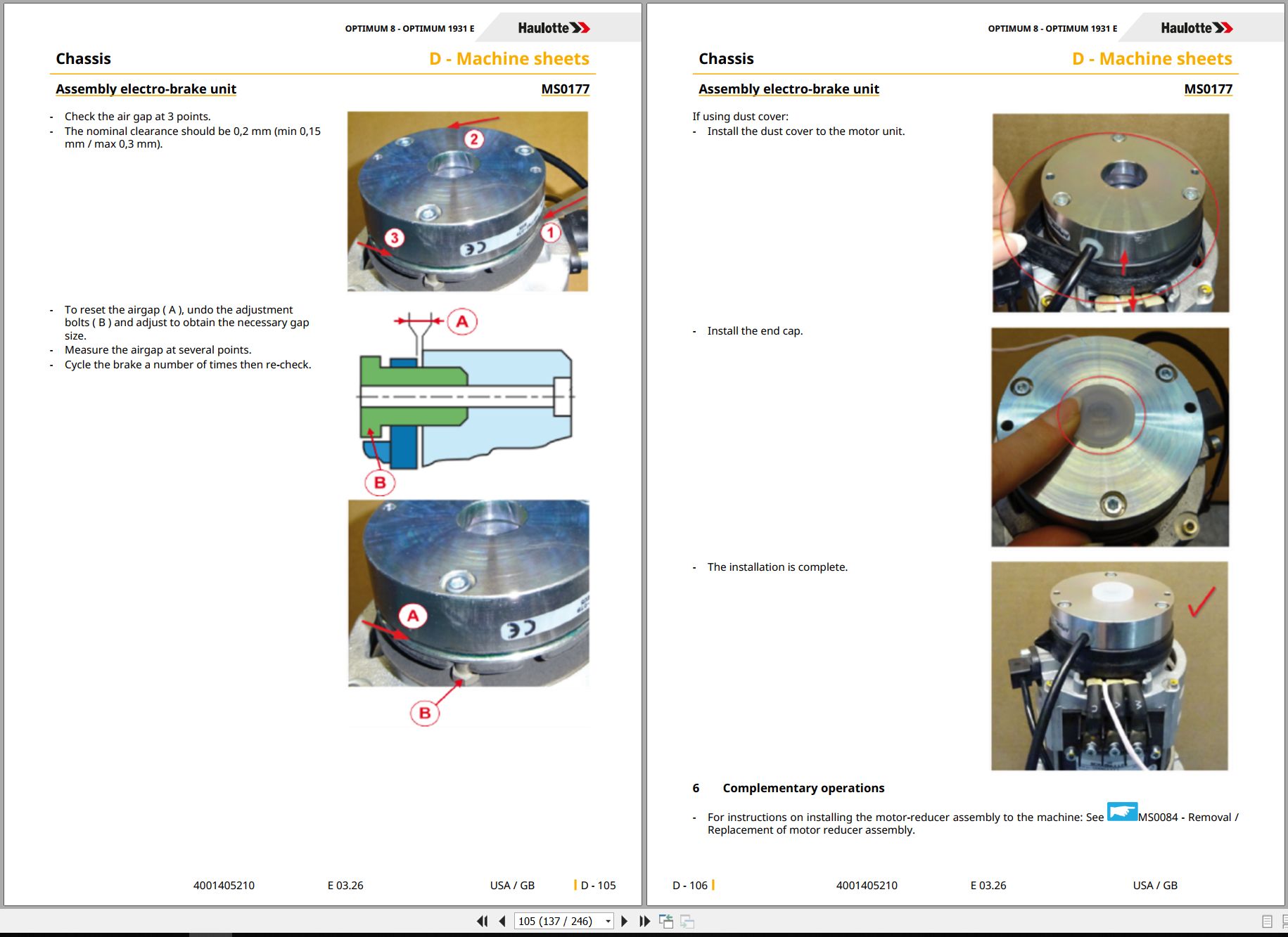
MS0177 – Assembly electro-brake unit
1 You will need
2 Level of knowledge required
3 Preliminary operation
4 Removal
5 Reinstall
6 Complementary operations
7 Checks
MS0178 – Brake unit protection installation
1 You will need
2 Level of knowledge required
3 Preliminary operation
4 Removal
4.1 Remove the counterweight
4.2 Treating a stuck brake
5 Reinstall
5.1 Installing the protection kit
5.2 Reinstall the counterweight
6 Checks
MS0179 – Assembly moto – reducer
1 You will need
2 Level of knowledge required
3 Preliminary operation
4 Assembly
5 Complementary operations
6 Checks
MS0242 – Check of tilt sensor
1 Warning
2 Risk prevention
3 You will need
4 Check of tilt sensor
MS0245 – Dismantling/Reassembling the Tilt Sensor
1 Warning
2 Risk prevention
3 You will need
4 Dis-assembly
5 Reassembly
6 Calibration
7 Additional operations
MS0283 – Assembly electro-brake unit (For the Asia-Pacific market only)
1 You will need
2 Level of knowledge required
3 Preliminary operation
4 Removal
5 Reinstall
6 Complementary operations
7 Checks
MS0314 – Maintenance implementation
1 Placing in configuration
MS0383 – Removal – Replacement of lithium-ion battery (For machines fitted with)
1 Warning
2 Risk prevention
3 You will need
4 Removal
Trouble shooting
1 Trouble shooting
1.1 Recommendations
1.2 Description
1.3 Requirements
1.4 Failures list
1.4.1 Failures list
1.4.2 List of failures per category
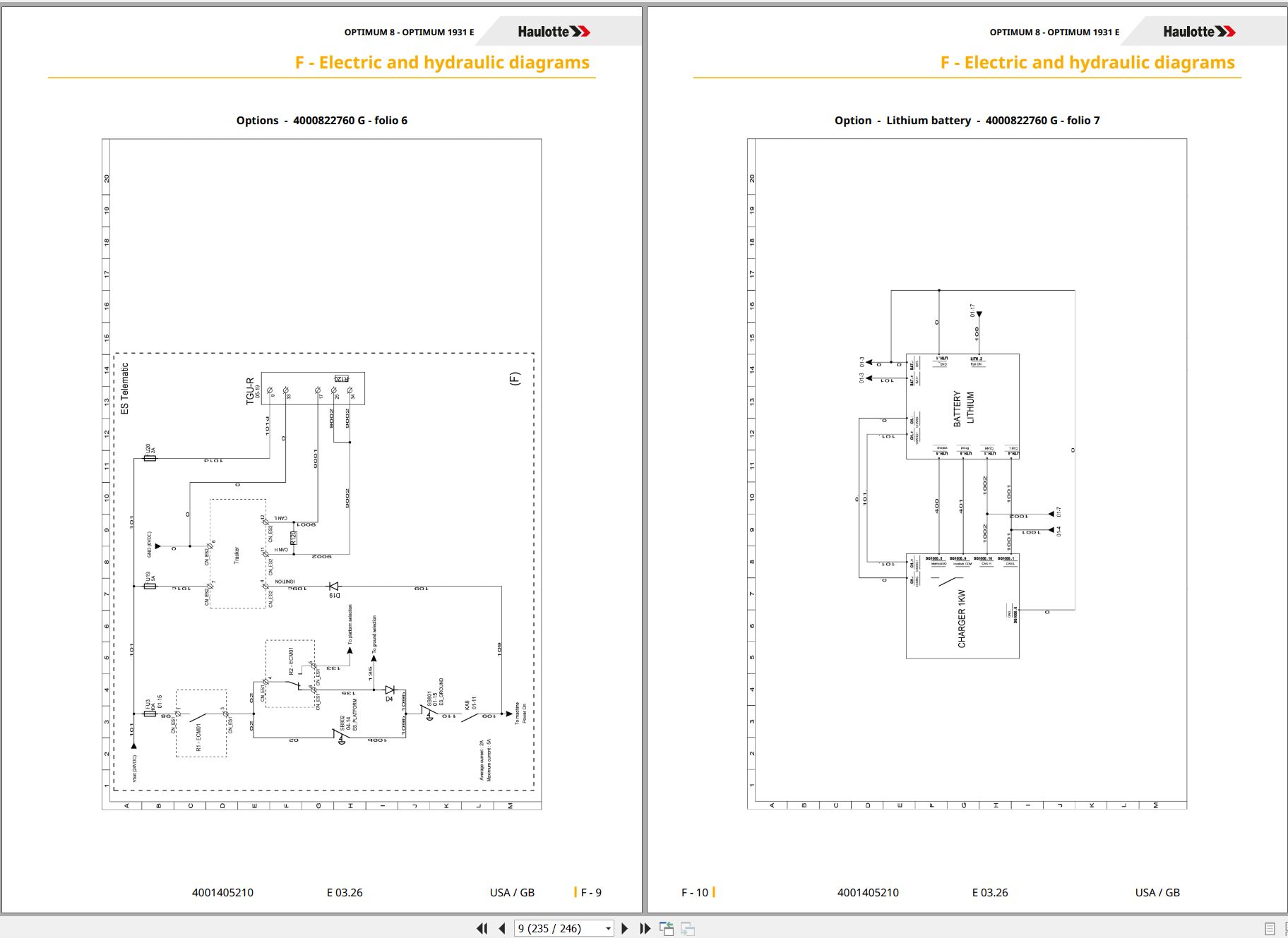
Electric and hydraulic diagrams
1 Wiring diagram
1.1 Electric diagram
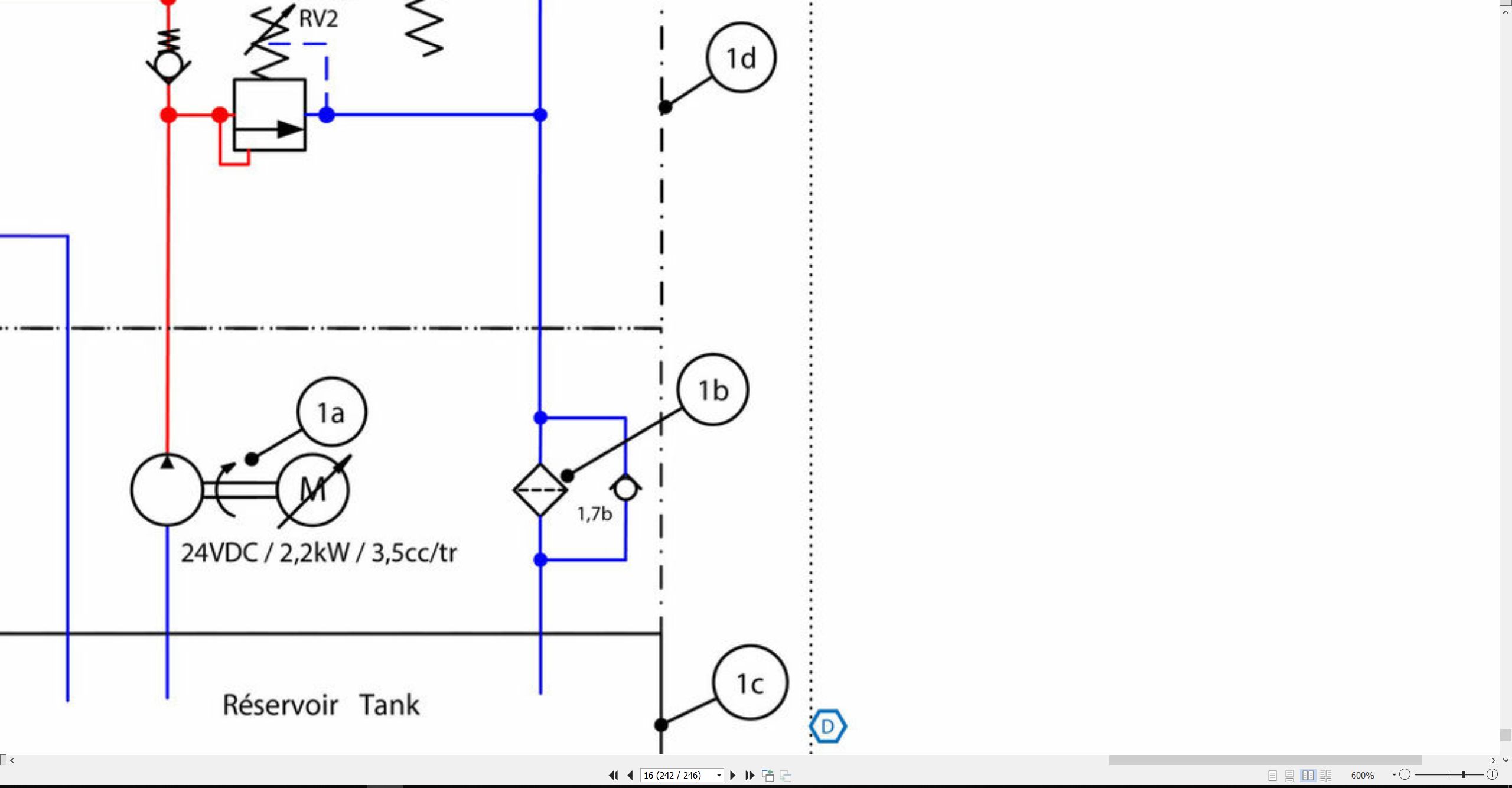
2 Hydraulic diagram
2.1 Hydraulic diagram
Records
1 Intervention register
Related Products
-
Liebherr Mining Excavators 76.3Gb PDF Updated 10.2021 Service Manuals DVD
USDLiebherr Mining Excavators 76.3Gb PDF Updated 10.2021 Service Manuals DVDSize: 76.3 Gb (PDF Files)Language: EnglishBrand: LiebherrFormat: PDFType of vehicle: Mining ExcavatorsType of manual: Service ManualUpdate: 10.2021OS: All WindowsAmount of DVD: 1 DVDNOTE: CONTACT TO EMAIL “admin@autoepcservice.com or autoepcservice@gmail.com” FOR PRICEREALEASE :
10.21.2021
-
Haulotte Work Platforms PDF 23.45 GB Updated [08.2021] Service, Maintenance & Operators Manual, Training & Spare Parts Manual DVD
Original price was: 600.340Current price is: 340. USDHaulotte Work Platforms PDF 23.45 GB Updated [08.2021] Service, Maintenance & Operators Manual, Training & Spare Parts Manual DVDSize: 23.45 GBLanguage: EnglishType: Haulotte Work Platforms and Telehandlers Service, Maintenance & Operators Manual, Training & Spare Parts Manual DVDType of Machine: Haulotte Work PlatformsFormat: PDFWindows: Window 7, Window 8, Window 10 32 & 64 BitAmount of DVD: 5 DVDDVD 1 Untill 2020DVD 2 2020-06.2020DVD 3 06.2020-23.09.2020DVD 4 09.2020-16.05.2021DVD 5 16.05.2021-06.08.2021 (2,25GB)Hot-43%
REALEASE :
11.08.2021
REALEASE :
11.08.2021
-
Haulotte Operating Maintenance Repair Parts Service Manuals PDF 7.03GB Collection
Original price was: 300.120Current price is: 120. USDThis is a service information package, you will need to use this to repair a vehicleHot-60%
REALEASE :
REALEASE :
-
Haulotte Service Manual Library PDF 4.10 GB
Original price was: 300.120Current price is: 120. USDThis is a service information package, you will need to use this to repair a vehicleHot-60%
REALEASE :
REALEASE :
-
Haulotte Work Platforms [10.2020] Service, Maintenance & Operators Manual, Training & Spare Parts Manual DVD
Original price was: 400.260Current price is: 260. USDHaulotte Work Platforms [10.2020] Service, Maintenance & Operators Manual, Training & Spare Parts Manual DVD Size: 19 Gb Language: English Type: Haulotte Work Platforms and Telehandlers Service, Maintenance & Operators Manual, Training & Spare Parts Manual Type of Machine: Haulotte Work Platforms Format: PDF Windows: Window 7, Window 8, Window 10 32 & 64 Bit Amount of DVD: 3 DVD 1 DVD Untill 2020 1 DVD 2020-06.2020 1 DVD 06.2020-23.09.2020 High Speed Link DownloadHot-35%
REALEASE :
07.10.2020
REALEASE :
07.10.2020
-
Liebherr Mining Excavator 15.07GB PDF Updated 10.2021 Operating Manual DVD
USDLiebherr Mining Excavator 15.07GB PDF Updated 10.2021 Operating Manual DVDSize: 15.07 Gb (PDF Files)Language: ENFormat: PDFBrand: LiebherrType of manuals: Operating ManualsType of vehicle: Mining VehicleDate Update: 10.2021OS: All WindowsQuantity of CD: 1 DVDHigh-Speed link DownloadREALEASE :
10.21.2021
-
Haulotte Work Platforms PDF 21,2GB Updated [06.2021] Service, Maintenance & Operators Manual, Training & Spare Parts Manual DVD
Original price was: 500.240Current price is: 240. USDHaulotte Work Platforms PDF 21,2GB Updated [06.2021] Service, Maintenance & Operators Manual, Training & Spare Parts Manual DVD Size: 21,2GB Language: English Type: Haulotte Work Platforms and Telehandlers Service, Maintenance & Operators Manual, Training & Spare Parts Manual DVD Type of Machine: Haulotte Work Platforms Format: PDF Windows: Window 7, Window 8, Window 10 32 & 64 Bit Amount of DVD: 4 DVD DVD 1 Untill 2020 DVD 2 2020-06.2020 DVD 3 06.2020-23.09.2020 DVD 4 09.2020-16.05.2021 High Speed Link DownloadHot-52%
REALEASE :
29.05.2021
REALEASE :
29.05.2021
-
Haulotte Work Platforms PDF 7.27 GB Updated 2022 Service, Maintenance & Operators Manual & Spare Parts Manual DVD 02
Original price was: 200.140Current price is: 140. USDHaulotte Work Platforms PDF 7.27 GB Updated 2022 Service, Maintenance & Operators Manual & Spare Parts Manual DVD 02Size: 7.27 GBLanguage: EnglishType of document:Haulotte Work Platforms and Telehandlers Maintenance manualHaulotte Work Platforms and Telehandlers Operators manualHaulotte Work Platforms and Telehandlers Service ManualHaulotte Work Platforms and Telehandlers Spare Parts manualType of Machine: Haulotte Work PlatformsFormat: PDFWindows: Window 7, Window 8, Window 10, Window 11 32 & 64 BitAmount of DVD: 1 DVD_02Hot-30%
REALEASE :
05.04.2022
REALEASE :
05.04.2022

