
2 ITEMSVIEW CART


Total: 70.00
Expert Support
Full Speed
100% Working
50 USD
Contents:
Responsibilities And Commitments
1 Foreword
2 Responsibilities
2.1 Owner’s Responsibility
2.1.1 Product Modification
2.2 Technician’s Responsability
3 Haulotte® Commitments
3.1 Haulotte Services®
3.2 Training
3.3 Product Information
3.3.1 Implementing Manufacturer Safety Campaigns
4 Conditions Of Warranty
Safety
1 General Safety Rules
1.1 Uncontrolled Movement Hazard
1.2 Electric Shock Hazards
1.3 Explosion / Fire Hazards
2 Safety Rules Energy Source Motorization
2.1 General Safety And Specific Interventions On The Thermal Engine
Familiarization
1 Haulotte Activ’screen 2
2 List Of Actuators And Sensors
2.1 Sensors And Actuators
3 Consumables (Oils - Fuels - Engine Oil - Coolant Level…)
3.1 Fuel
3.1.1 General Specifications
3.1.2 Other Fuels
3.2 Engine Oil
3.3 Hydraulic Oil
3.4 Axle, Gearbox And Reducer Oil
3.5 Coolant
3.6 Cylinder Storage Oil
3.7 Grease
3.8 Marine Protection
3.9 Consumables
4 Movement Speed
Machine Sheets
Machine Sheets
Ms0001 – Structural Part Inspection
1 Warning
2 Risk Prevention
3 You Will Need
4 Control And Maintenance
4.1 Daily Inspection
4.2 Major Inspection
4.3 Functional Tests
4.4 Dynamic Tests
4.5 Structural Test
Ms0002 – Pins And Bearing Inspection
1 Warning
2 Risk Prevention
3 You Will Need
4 Control And Maintenance
5 Criteria Of Replacement
6 Procedure Of Reassembly
6.1 Pins And Bushes
6.2 Bearings
Ms0003 – Cylinder Inspection
1 Warning
2 Risk Prevention
3 You Will Need
4 Control And Maintenance
4.1 Visual Inspections
4.2 Functional Tests
4.3 Major Inspection
Ms0004 – Braking Test Procedure
1 Warning
2 Risk Prevention
3 You Will Need
4 Test Procedure
Ms0009 – Fuel Tank - Filling-Up
1 Warning
2 Risk Prevention
3 You Will Need
4 Consumable
5 Filling
Ms0029a – Kubota Diesel Engine
1 Product Information
2 Localization Identification Plate
3 Names Of Parts
4 Operating The Engine
4.1 Starting The Engine (Normal)
4.2 Checks During Operation
4.2.1 Oil Pressure Lamp
4.2.2 Fuel
4.2.3 Immediately Stop The Engine If:
4.3 Reversed Engine Revolution And Remedies
4.3.1 How To Tell When The Engine Starts Running Backwards
4.3.2 Remedies
5 Maintenance
5.1 Lubricating Oil
6 Periodic Service
6.1 Fuel
6.1.1 Fuel Level Check And Refueling
6.1.2 Air Bleeding The Fuel System
6.1.3 Checking The Fuel Pipes
6.2 Radiator
6.2.1 Checking Radiator Hoses And Clamp
6.2.2 Precaution At Overheating
6.2.3 Cleaning Radiator Core (Outside)
6.2.4 Anti-Freeze
7 Carriage And Storage
7.1 Carriage
7.2 Storage
8 Troubleshooting
Ms0029c – Perkins Diesel Engine
1 Localization Identification Plate
2 Safety Precautions
3 Technical Specifications
4 Names Of Parts
5 Operating The Engine
5.1 Starting The Engine (Normal)
5.2 Checks During Operation
5.2.1 Oil Pressure Lamp
5.2.2 Fuel
5.2.3 Immediately Stop The Engine If:
5.3 Reversed Engine Revolution And Remedies
5.3.1 How To Tell When The Engine Starts Running Backwards
5.3.2 Remedies
6 Maintenance
7 Fuel
8 Oil
8.1 Engine Oil Classification
8.2 Engine Oil
9 Anti-Freeze
10 Carriage And Storage
10.1 Carriage
10.2 Storage
11 Troubleshooting
Ms0031 – Overload System
1 You Will Need
2 Level Of Knowledge Required
3 Safety Instructions
4 Periodic Inspection
5 Calibration Procedure
5.1 Configuring The Machine Before Start Calibration
5.2 Connection And Use Console
5.3 Procedure
5.4 Reset Of The Zero (Empty Cage) Value
5.5 Calibration Using A Fixed Known Weight Of 250 Kg (551 Lbs)
5.6 Calibration With A Known Weight Of Any Value Between 75 Kg (165 Lbs) And 300 Kg (662 Lbs)
5.7 Fault Codes Linked To The Overload System
6 Checks
Ms0133 – Universal Plug
1 You Will Need
2 Procedure
Ms0164 – Weighing Adjustment Procedure (Calibration)
1 Concerned Area
2 Warning
3 Risk Prevention
4 You Will Need
5 Assembly Of The Vibrating Wire Load Cell
6 Assembly Of The Vibrating Wire Load Cell
7 Calibration Procedure
7.1 Tare Calibration
7.2 Calibration With A Load From 75 Kg To 300 Kg
7.3 Checks
7.3.1 Control The Load With Haulotte Diag
7.3.2 Control The Overload Alarm
Ms0223 – Check Of Tilt Sensor
1 Concerned Area
2 Warning
3 Risk Prevention
4 You Will Need
5 Check Of Tilt Sensor
Ms0285 – Maintenance Implementation
1 Placing In Configuration
Ms0286 – Remove – Reinstall The Hydraulic Rotation Motor
1 Concerned Area
2 Warning
3 Risk Prevention
4 You Will Need
5 Removal
6 Re-Installation
7 Additional Operations
Ms0287 – Remove – Reinstall The Hydraulic Pump
1 Concerned Area
2 Warning
3 Risk Prevention
4 You Will Need
5 Removal
6 Re-Installation
7 Additional Operations
Ms0288 – Removing/Re-Installing The Oscillating Axle Actuator
1 Concerned Area
2 Warning
3 Risk Prevention
4 You Will Need
5 Removal
6 Re-Installation
7 Additional Operations
Ms0289 – Remove/Re-Install The Hydraulic Motor
1 Concerned Area
2 Warning
3 Risk Prevention
4 You Will Need
5 Removal
6 Re-Installation
7 Additional Operations
Ms0290 – Remove – Reinstall The Drive Shaft
1 Concerned Area
2 Warning
3 Risk Prevention
4 You Will Need
5 Removal
6 Re-Installation
7 Additional Operations
Ms0291 – Remove/Re-Install Slip Ring (Electric Rotary Coupling)
1 Concerned Area
2 Warning
3 Risk Prevention
4 You Will Need
5 Removal
6 Re-Installation
7 Additional Operations
Ms0292 – Remove – Reinstall The Axle Assembly
1 Concerned Area
2 Warning
3 Risk Prevention
4 You Will Need
5 Removal
5.1 Removing The Front Axle
5.2 Removing The Rear Axle
6 Re-Installation
7 Additional Operations
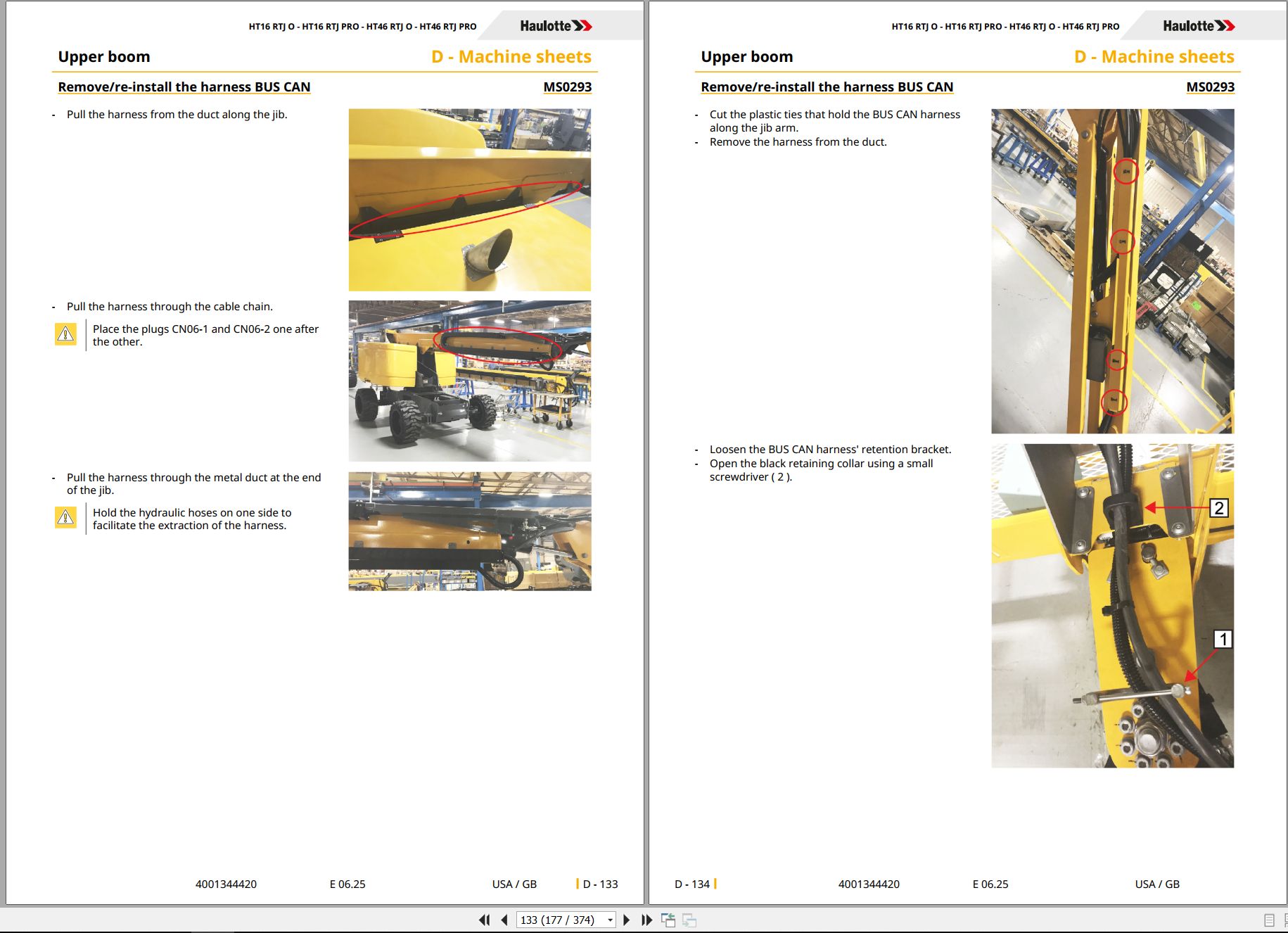
Ms0293 – Remove/Re-Install The Harness Bus Can
1 Concerned Area
2 Warning
3 Risk Prevention
4 You Will Need
5 Removal
6 Re-Installation
7 Additional Operations
Ms0294 – Removing / Replacing The Pads
1 Concerned Area
2 Warning
3 Risk Prevention
4 You Will Need
5 Removal
5.1 Front Pads Replacement
5.2 Rear Pads Replacement
6 Re-Installation
7 Additional Operations
Ms0295 – Remove – Replace Telescope Cylinder
1 Concerned Area
2 Warning
3 Risk Prevention
4 You Will Need
5 Removal
6 Re-Installation
7 Additional Operations
Ms0296 – Remove/Re-Install Output Compensation Cylinder
1 Concerned Area
2 Warning
3 Risk Prevention
4 You Will Need
5 Removal
6 Re-Installation
7 Additional Operations
Ms0297 – Remove/Re-Install Input Compensation Cylinder
1 Concerned Area
2 Warning
3 Risk Prevention
4 You Will Need
5 Removal
6 Re-Installation
7 Additional Operations
Ms0298 – Remove – Replace The Boom/Jib/Box Assembly
1 Concerned Area
2 Warning
3 Risk Prevention
4 You Will Need
5 Removal
6 Re-Installation
7 Additional Operations
Ms0299 – Removal – Replacement Of The Platform
1 Concerned Area
2 Warning
3 Risk Prevention
4 You Will Need
5 Removal
6 Re-Installation
7 Additional Operations
Ms0300 – Removal – Replacement Of The Jib And Platform
1 Concerned Area
2 Warning
3 Risk Prevention
4 You Will Need
5 Removal
6 Re-Installation
7 Additional Operations
Ms0301 – Removing The Boom Lifting Cylinder
1 Concerned Area
2 Warning
3 Risk Prevention
4 You Will Need
5 Removal
6 Re-Installation
7 Additional Operations
Ms0302 – Remove/Re-Install Jib Cylinder
1 Concerned Area
2 Warning
3 Risk Prevention
4 You Will Need
5 Removal
6 Re-Installation
7 Additional Operations
Ms0303 – Remove/Re-Install Rotary Actuator
1 Concerned Area
2 Warning
3 Risk Prevention
4 You Will Need
5 Removal
6 Re-Installation
7 Additional Operations
Ms0304 – Remove – Reinstall The Screen Activ’screen Cat2
1 Concerned Area
2 Warning
3 Risk Prevention
4 You Will Need
5 Removal
6 Re-Installation
7 Additional Operations
Ms0305 – Remove – Replace Counterweight
1 Concerned Area
2 Warning
3 Risk Prevention
4 You Will Need
5 Removal
6 Re-Installation
7 Additional Operations
Ms0306 – Disassembly – Assembly Activ’ Shield Bar
1 Concerned Area
2 Warning
3 Risk Prevention
4 You Will Need
5 Removal
6 Re-Installation
7 Additional Operations
Ms0307 – Removal – Replacement Of Starter Battery
1 Concerned Area
2 Warning
3 Risk Prevention
4 You Will Need
5 Removal
6 Re-Installation
7 Additional Operations
Ms0308 – Remove – Replace Load Cell
1 Concerned Area
2 Warning
3 Risk Prevention
4 You Will Need
5 Removal
6 Re-Installation
7 Additional Operations
Ms0309 – Sensor Ils Adjustment
1 Concerned Area
2 Warning
3 Risk Prevention
4 You Will Need
5 Sensor  Adjustment-Telescope
6 Sensor  Adjustment-Upper Boom
7 Sensor  Adjustment-Dual Load
Ms0310 – Pressure Adjustment
1 Warning
2 Risk Prevention
3 You Will Need
4 Pressure Adjustment
5 Pressure Plug Location
Ms0396 – Overload System - Instrumented Axis
1 Concerned Machines
2 Level Of Knowledge Required
3 Safety Instructions
4 You Will Need
5 Location Of The Load Pin Sensor
6 When Should You Make A Calibration
7 Configuring The Machine Before Start Calibration
8 Procedure
9 Offset Of Load Management System With Platform Empty
10 Gain Of Load Management System With Fixed Weight
11 Gain Of Load Management System With Adjustable Weight
12 Fault Codes Linked To The Overload System
13 Checks
Ms0503 – Removal – Refitting Of The Weighing System Force Sensor
1 Concerned Area
2 Warning
3 Risk Prevention
4 You Will Need
5 Removal
6 Re-Installation
7 Additional Operations
Trouble Shooting
1 Trouble Shooting
1.1 Recommendations
1.2 Description
1.3 Requirements
1.4 Failures List
1.4.1 List Of Failures Per Category
2 Legend
2.1 Pcb Turret
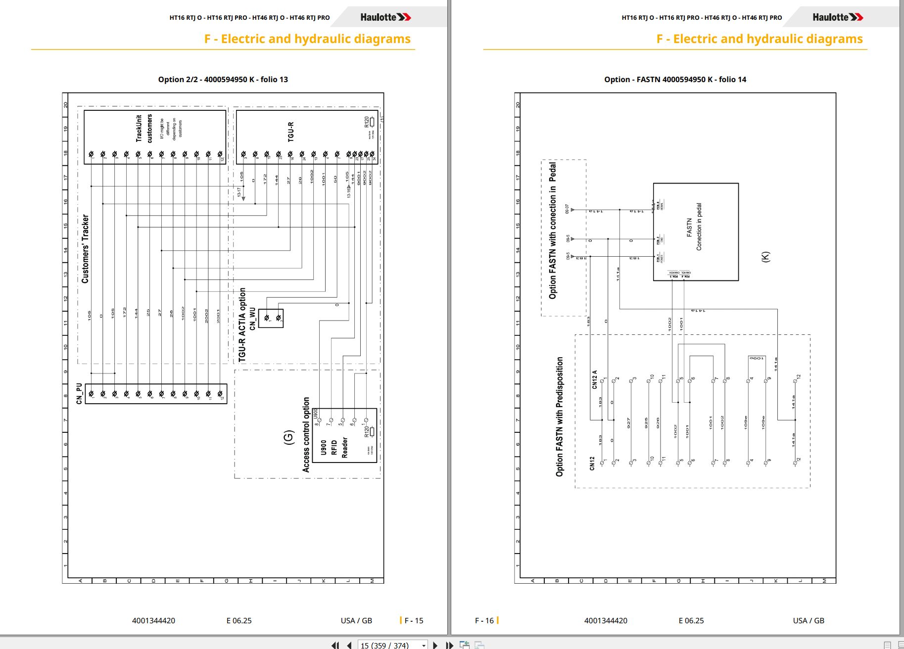
Electric And Hydraulic Diagrams
1 Wiring Diagram
1.1 Electric Diagram
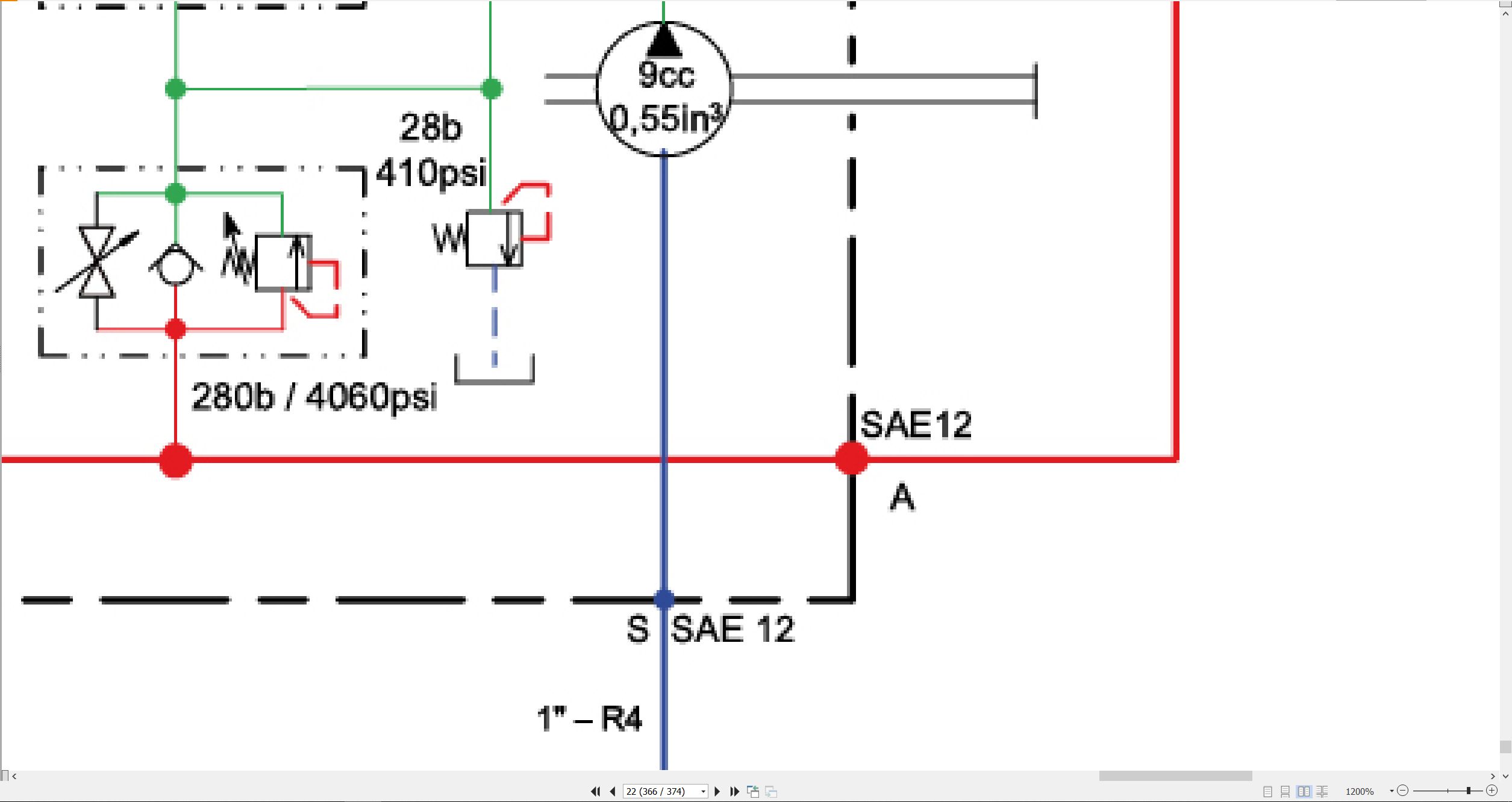
2 Hydraulic Diagram
2.1 Hydraulic Diagram
Records
1 Intervention Register

REALEASE :
REALEASE :

REALEASE :
REALEASE :
REALEASE :
10.21.2021

REALEASE :
29.05.2021
REALEASE :
29.05.2021

REALEASE :
07.10.2020
REALEASE :
07.10.2020

REALEASE :
05.04.2022
REALEASE :
05.04.2022

REALEASE :
11.08.2021
REALEASE :
11.08.2021
REALEASE :
10.21.2021
 Automotive - Heavy Equipment - Truck & Bus - Forklift - Crane
