
16 ITEMSVIEW CART


Total: 1,705.00
Expert Support
Full Speed
100% Working
20 USD
Contents:
Foreword
1 Foreword
2 User responsibility
2.1 Owner’s responsibility
2.2 Employer’s responsibility
2.3 Trainer’s responsibility
2.4 Operator’s responsibility
3 Safety
3.1 Safety instructions
3.1.1 Incorrect use
3.1.2 Falling Hazards
3.1.3 Overturning / Tip-over Hazards
3.1.4 Risk of electric shock (electrocution)
3.1.5 Explosion / Fire Hazards
3.1.6 Crushing / Collision Hazards
3.1.7 Risk of involuntary movements
4 Safety inquiries
5 Incident notification
6 Compliance
6.1 Product modification
6.1.1 Implementing manufacturer safety campaigns
6.2 Product specifications
6.3 Change of Ownership Notification
6.4 Declaration of conformity
6.4.1 Declaration of conformity - All machines
6.4.2 Declaration of conformity - Thermal platforms
Familiarization
1 General safety
1.1 Intended use
1.2 Decal content
1.3 Level of severity
1.4 Symbols legend and definitions
1.5 Symbols and colors
2 Models description
3 Primary machine components
3.1 Layout
3.2 Ground control box
3.2.1 Layout - Color screen display
3.2.2 HAULOTTE Activ’Screen 2
3.3 Platform control box
3.3.1 Layout
3.3.2 Display Panel (LED’SÂ 101, 117)
3.4 DPF (Diesel Particle Filter) (If equipped)
3.4.1 Kubota engine
3.4.2 Deutz engine
3.4.3 Automatic regeneration
3.4.4 Manual regeneration
3.4.5 To inhibit regeneration
3.4.6 To stop manual regeneration
4 Performance Specifications
4.1 Technical characteristics
4.2 Engine specifications
4.2.1  Kubota engines
4.2.2  Deutz engines
4.3 Working area / Range of motion
5 Decals and markings locations
Pre-operation inspection
1 Recommendations
2 Working area assessment
3 Inspection and Functional test
3.1 Daily inspection
4 Safety functional checks
4.1 E-Stop button check
4.2 Activation of controls
4.3 Fault detector
4.3.1 Indicators/LED’s test
4.3.2 Buzzers test
4.4 Automatic engine cut-out
4.5 Overload sensing system
4.6 Oscillating axles (If equipped)
4.7 Slope warning device
4.8 Travel speed limitation
4.9 On-board electronics
4.10 Load selection system (if fitted)
4.11 Braking test
4.12 Overload test
Operation instructions
1 Operation
1.1 Introduction
1.2 Major description
1.3 Operation from the ground control box (Auxiliary station)
1.4 Operation from the platform control box (Main station)
2 Ground control box
2.1 To start and stop the machine - Diesel engine
2.2 To start and stop the machine - Petrol / gas (Propane) Engine
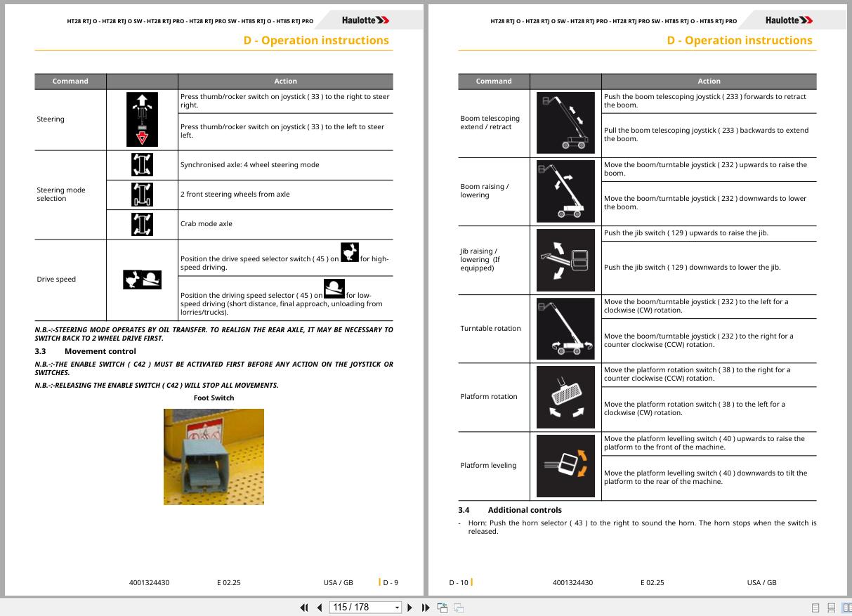
2.3 Movement control
2.4 Additional controls
3 Platform control box
3.1 To start and stop the machine
3.1.1 To start the machine
3.1.1.1 To stop the engine
3.1.1.2 If engine is stopped by Stop Emission System
3.2 Drive and steer control
3.3 Movement control
3.4 Additional controls
3.4.1 Stop Emission System
3.4.2 Activ’ Lighting System
3.4.3 Dual load selector (if fitted)
4 Rescue and emergency procedures
4.1 In case of power loss
4.2 To rescue operator in platform
4.3 Operation of overriding system from ground control box
4.4 No power available
5 Transportation
5.1 Transport configuration
5.2 Machine stowage for transport , HT28 RTJ O, HT28 RTJ O SW, HT85 RTJ O, HT28 RTJ PRO, HT28 RTJ PRO SW, HT85 RTJ PRO
5.3 Unloading
5.4 Towing
5.4.1 Disengaging the drive hubs
5.4.2 Re-engaging the drive hubs
5.5 Storage
5.6 Lifting operation
6 Cold Weather Recommendations
6.1 Engine oil
6.2 Hydraulic oil
General Specifications
1 Machine dimensions
2 Major component masses
3 Acoustics and vibrations
4 Wheel/Tire assembly
4.1 Technical specifications
4.2 Inspection and maintenance
5 Options
5.1 Compatibility
5.2 Platform
5.2.1 Swing gate
5.2.1.1 Description
5.2.1.2 Safety precautions
5.2.1.3 Pre-operation instructions
5.2.1.4 Description
5.3 On-board generator
5.3.1 Description
5.3.2 Characteristics
5.3.3 Safety precautions
5.3.4 Pre-operation inspection
5.3.5 Operation
5.4 Glazier’s kit
5.4.1 Description
5.4.2 Characteristics
5.4.3 Safety precautions
5.4.4 Pre-operation inspection
5.4.5 Operation
5.4.6 Assembly/Dis-assembly
5.4.7 Specific decals
5.5 Welder’s kit
5.5.1 Description
5.5.2 Characteristics
5.5.3 Safety precautions
5.5.4 Pre-operation inspection
5.5.5 Operation
5.5.6 Assembly-Dis-assembly
5.5.7 Specific decals
5.6 Plumber’s kit
5.6.1 Description
5.6.2 Characteristics
5.6.3 Safety precautions
5.6.4 Pre-operation inspection
5.6.5 Operation
5.6.6 Assembly-Dis-assembly
5.6.7 Specific decals, optional
5.7 Activ’ Shield Bar -  Secondary guarding system (If fitted)
5.7.1 Description
5.7.2 Characteristics
5.7.3 Safety precautions
5.7.4 Pre-operation inspection
5.7.5 Operation
5.7.6 Specific decals
5.8 Sand tires
5.8.1 Technical specifications
5.8.2 Inspection and maintenance
5.8.3 Specific decal(s)
Maintenance
1 General
2 Maintenance Schedule
3 Inspection program
3.1 General program
3.2 Daily inspection
3.3 Periodic inspection
3.4 Reinforced inspection
3.5 Major inspection
4 Repairs and adjustments
Other information
1 Conditions of warranty
2 Subsidiary contact information
2.1 California warning
Records
1 Intervention register

REALEASE :
05.04.2022
REALEASE :
05.04.2022
REALEASE :
10.21.2021

REALEASE :
REALEASE :
REALEASE :
10.21.2021

REALEASE :
REALEASE :

REALEASE :
07.10.2020
REALEASE :
07.10.2020

REALEASE :
29.05.2021
REALEASE :
29.05.2021

REALEASE :
11.08.2021
REALEASE :
11.08.2021
 Automotive - Heavy Equipment - Truck & Bus - Forklift - Crane
