
0 ITEMSVIEW CART


✓
Expert Support
✓
Full Speed
✓
100% Working
International Truck CF500 CF600 Electrical Diagram S08317 2006
Size: 3.13 MB
Format: PDF
Language: English
Brand:
Type of Machine: Truck
Type of Manual: Electrical Diagram, Circuit Diagrams
Model: CF 500 Start Date: 02/01/2006 End Date: 08/31/2007; CF 600 Start Date: 02/01/2006 End Date: 08/31/2007
Part Number: S08317
Publication Date: 2006
Number of Pages: 90 Pages
30 USD
- Description
Description
Contents:
1. Instructions And Charts (Chapter 1)
1.1. Circuit Diagram Instructions, P. 1
1.2. Circuit Diagram Instructions, P. 2
1.3. Circuit Diagram Instructions, P. 3
1.4. Relay Functions And Wiring Guide, P. 4
1.5. International V6 Engine Controller Pin Number Identification, P. 5
1.6. Power Distribution Box, P. 6
1.7. Power Distribution Box, P. 7
1.8. In-Cab Relay Box, P. 8
1.9. Lamp Bulb Chart, P. 9
2. 12 Volt Power Distribution Circuit Diagrams (Chapter 2)
2.1. Battery Feeds, P. 1
2.2. Battery Feeds, P. 2
2.3. Battery Feeds, P. 3
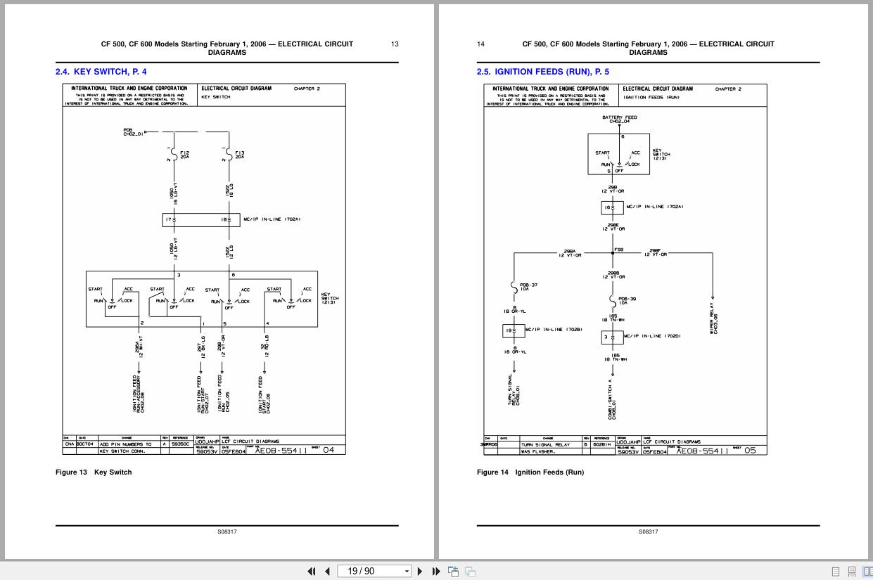
2.4. Key Switch, P. 4
2.5. Ignition Feeds (Run), P. 5
2.6. Ignition Feeds (Start), P. 6
2.7. Ignition Feeds (Run-Start), P. 7
2.8. Ignition Feeds (Run-Accessory), P. 8
2.9. Grounds (Main Chassis), P. 9
2.10. Grounds (Main Chassis), P. 10
2.11. Grounds (Rear Chassis), P. 11
2.12. Grounds (Ip), P. 12
2.13. Grounds (Ip), P. 13
2.14. Cab Grounds (Roof, Floor), P. 14
2.15. J1708 Data Link, P. 15
2.16. J1939 Data Link, P. 16
2.17. J2284 Data Link, P. 17
2.18. Diagnostic Connectors, P. 18
3. Cab Accessories (Chapter 3)
3.1. Cigar Lighter, P. 1
3.2. Power Windows, P. 2
3.3. Power Doors, P. 3
3.4. Horn, P. 4
3.5. Radio, P. 5
3.6. Windshield Wiper And Washer Pump, P. 6
3.7. Door Ajar Switch And Dome Light, P. 7
4. 12v Charging And Cranking System (Chapter 4)
4.1. Charging And Cranking — International V6 Engine, P. 1
5. Fans And Engine Accessories (Chapter 5)
5.1. Hfcm Module — International V6 Engine, P. 1
5.2. Fuel Tanks — Dual Tank, P. 2
5.3. Fuel Tanks — Left And Aft Tank, P. 3
6. Electronic Engines (Chapter 6)
6.1. International V6 Power And Ground System, P. 1
6.2. International V6 Cruise Control, P. 2
6.3. International V6 Accelerator Pedal, P. 3
7. Clusters And Warning Lights (Chapter 7)
7.1. Cluster Connector A, P. 1
7.2. Cluster Connector A, P. 2
7.3. Cluster Connector B, P. 3
7.4. Cluster Connector B, P. 4
8. Lights (Chapter 8)
8.1. Main Light Switch, Hazard Switch, P. 1
8.2. Marker, Front Park And Turn Lights, P. 2
8.3. Rear Tail, Turn, Stop And Backup Lights, P. 3
8.4. Fog Lights, P. 4
8.5. Headlights, P. 5
8.6. Panel Lights, P. 6
9. Chassis Accessories (Chapter 9)
9.1. Antilock Brake System (Abs), P. 1
9.2. Body Builder Customer Access Circuits (Boc), P. 2
9.3. Body Builder Lighting Circuits (Boc), P. 3
9.4. Body Builder (Eof), P. 4
9.5. Brake Systems: Fluid, Pressure And Pedal Switch, P. 5
9.6. Brake Systems: Electric Trailer Brakes, P. 6
10. Transmission (Chapter 10)
10.1. Transmission Control Module Connector, P. 1
10.2. Tcm To Transmission Bulkhead Connector, P. 2
11. Climate Control (Chapter 11)
11.1. Hvac System, P. 1
11.2. A/C Clutch, P. 2
11.3. Pusher Fan, P. 3
12. Connector Composites (Chapter 12)
12.1. Connector Composites (1), (2), (3), (4), (5), (101), (102), (103), (104), (105), (106), P.1
12.2. Connector Composites (1g), (201), (202a), (202c), (203), (204), P. 2
12.3. Connector Composites (205a), (205b), (206), (207), (208), (209), P. 3
12.4. Connector Composites (211), (212), (213), (214), (215), (217a), (217b), P. 4
12.5. Connector Composites (220), (222), (223), (225), (226), (227), (228), (229), (233), (234), P. 5
12.6. Connector Composites (235), (236b), P. 6
12.7. Connector Composites (237), (238), (239), (240), (241), (242a), (242b), P. 7
12.8. Connector Composites (2g), (3g), (243), (244), (245), (246), (247), (248),(249), (300g), (301g), (302g), P. 8
12.9. Connector Composites (301), (301a), (301b), (301d), (304d), (304e), P. 9
12.10. Connector Composite (306), P. 10
12.11. Connector Composites (308), (309), (310), (313), P. 11
12.12. Connector Composites (315), (316), (317), (318), (401), (402), P. 12
12.13. Connector Composites (403), (404), (410), (411), (412), (413), (4g), (500), P. 13
12.14. Connector Composites (502), (503), (504), (506), (507), (508), (509), (510), P. 14
12.15. Geometry Removed, P. 15
12.16. Connector Composites (700), (702a), P. 16
12.17. Connector Composites (701), (702b), P. 17
12.18. Connector Composites (702d), P. 18
12.19. Connector Composites (703), (704), P. 19
12.20. Connector Composites (705), P. 20
12.21. Connector Composites (705), P. 21
12.22. Connector Composites (705), (706), (707), P. 22
Related Products
-
International Truck OnCommand Service Manual Diagrams PDF DVD
Original price was: 200.60Current price is: 60. USDInternational Truck OnCommand 2.13 GB PDF Service Manual & DiagramsSize: 2,13GbLanguages: EnglishFormat: PDFBrand: International TruckTypes of Vehicle: TruckTypes of Manuals: Service Manual & DiagramsQuantity of CD: 1 DVDOS: All WindowHot-70%
REALEASE :
14.04.2022
REALEASE :
14.04.2022
-
International Truck MV Series TC Bus Interactive Schematics 0000018824 2021
30 USDSize: 107.19 MBFormat: PDFLanguage: EnglishBrand:Type of Machine: TruckType of Manual: Interactive SchematicsModel: International MV Series TC Bus TruckBuilt: 1/1/2018 To 12/10/2021Built: 2018 – 2021Part Number: 0000018824Publication Date: 2021Number of Pages: 2394 Pages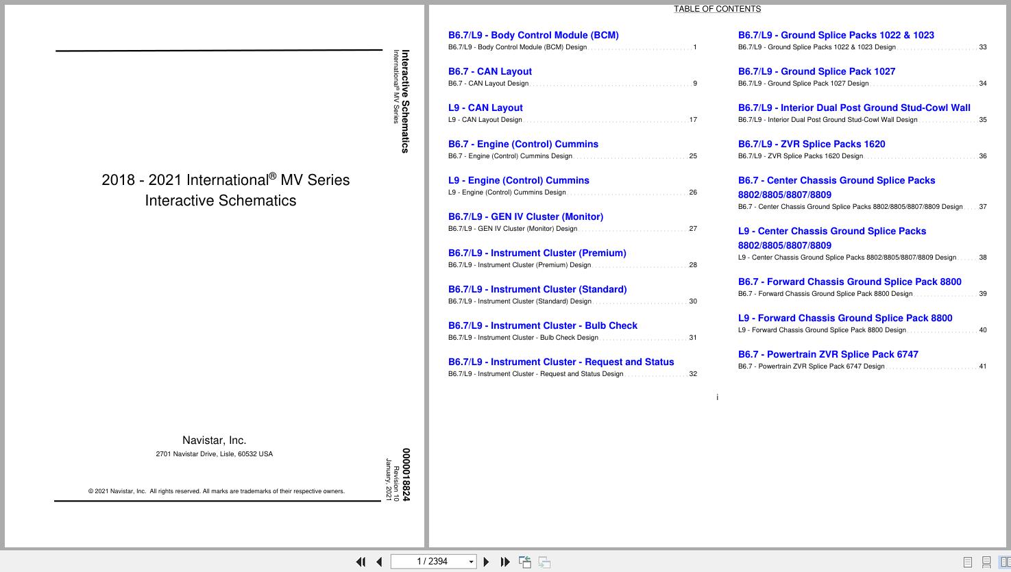
REALEASE :
REALEASE :
-
International Truck eMV Series Body Integration Quick Reference Guide
30 USDSize: 5.95 MBFormat: PDFLanguage: EnglishBrand:Type of Machine: TruckType of Manual: Quick Reference GuideModel: International eMV Series Body Integration TruckPublication Date: 2022Number of Pages: 46 Pages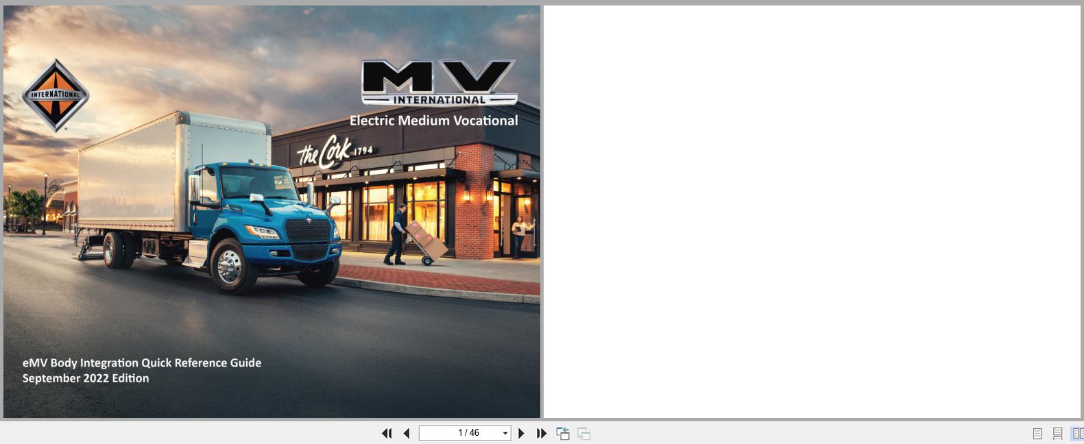
REALEASE :
REALEASE :
-
International Truck PayStar 5500i to 9900i Series Electrical Diagram 0000011981 2015
30 USDSize: 24.27 MBFormat: PDFLanguage: EnglishBrand:Type of Machine: TruckType of Manual: Electrical Diagram, Circuit DiagramModel: International PayStar 5500i Series, 5600i Series, 5900i Series, 9200i Series, 9900i Series – ChassisBuilt: March 1, 2007 and AfterPart Number: 0000011981 (Supersedes S08326)Publication Date: 2015Number of Pages: 450 Pages
REALEASE :
REALEASE :
-
International Truck eMV Series Interactive Schematics 0000018831 2025
50 USDSize: 22.29 MBFormat: PDFLanguage: EnglishBrand:Type of Machine: TruckType of Manual: Interactive SchematicsModel: International eMV Series TruckBuilt: 8/3/2021 To 12/31/2025Part Number: 0000018831Publication Date: 2025Number of Pages: 813 Pages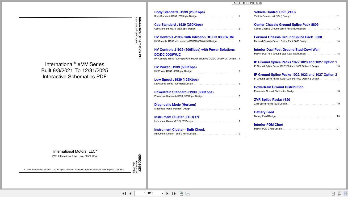
REALEASE :
REALEASE :
-
International Truck TC Commercial Bus Body Builder Book PBB-43200 2022
30 USDSize: 4.95 MBFormat: PDFLanguage: EnglishBrand:Type of Machine: TruckType of Manual: Body Builder BookModel: International TC Commercial Bus TruckPart Number: PBB-43200Publication Date: 2022Number of Pages: 130 Pages
REALEASE :
REALEASE :
-
International Truck eMV Series Electrical Systems Integration Guide 2025
50 USDSize: 7.53 MBFormat: PDFLanguage: EnglishBrand:Type of Machine: TruckType of Manual: Electrical Systems Integration GuideModel: International eMV Series TruckPublication Date: 2025Number of Pages: 179 Pages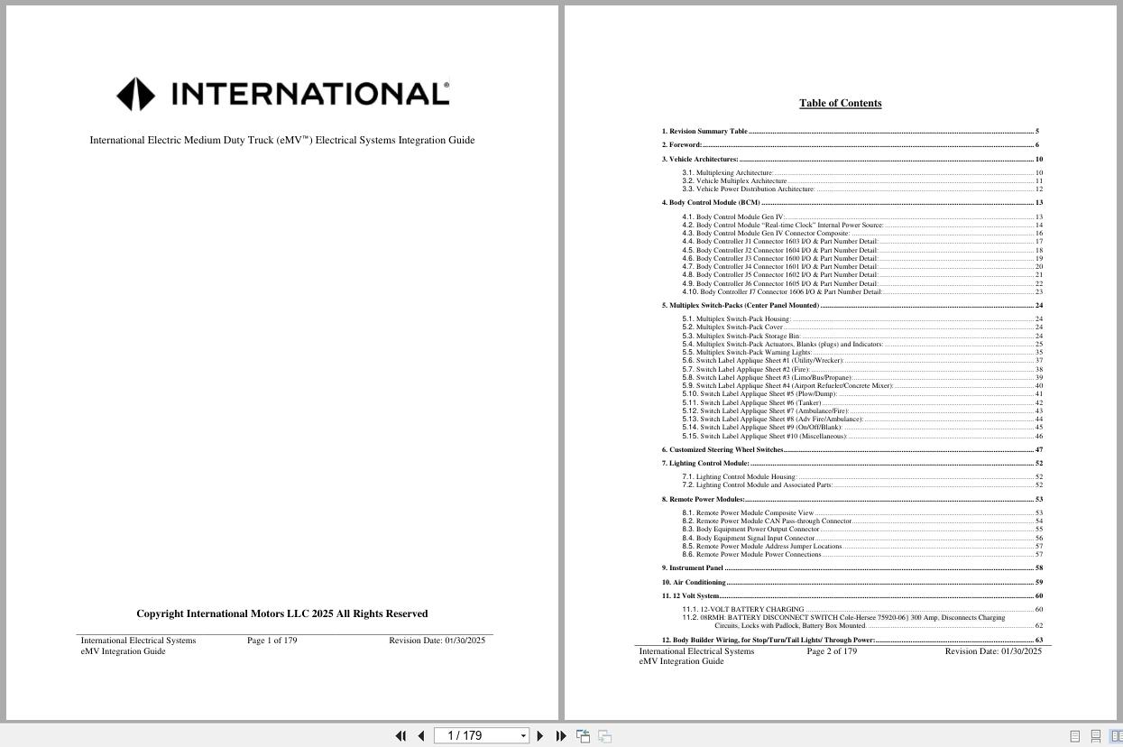
REALEASE :
REALEASE :
-
International Truck PayStar 5900 Electrical Diagram 0000002441 2021
30 USDSize: 12.49 MBFormat: PDFLanguage: EnglishBrand:Type of Machine: TruckType of Manual: Electrical Diagram, Circuit DiagramModel: International PayStar 5900 TruckEngine Family: MaxxForce 11/13, 15L, N13 or ISX15 Engines with SCRPart Number: 0000002441 (Supersedes S08352)Publication Date: 2021Number of Pages: 348 Pages
REALEASE :
REALEASE :