
0 ITEMSVIEW CART

✓
Expert Support
✓
Full Speed
✓
100% Working
International Truck HV HX LT MV RH 2021 Electrical Systems Integration Guide
Size: 34.03 MB
Format: PDF
Language: English
Brand:
Type of Machine: Truck
Type of Manual: Electrical Systems Integration Guide
Model: International HV HX LT MV RH 2021 Electrical Systems Truck
Publication Date: 2025
Number of Pages: 903 Pages
30 USD
- Description
Description
Contents:
- Revision Summary Table
- Forward:
- Vehicle Architectures:
3.1. Multiplexing Architecture:
3.2. Vehicle Multiplex Architecture
3.3. Vehicle Power Distribution Architecture: - Body Control Module (BCM)
4.1. Body Control Module Gen IV:
4.2. Body Control Module “Real-time Clock” Internal Power Source:
4.3. Body Control Module Gen IV Connector Composite:
4.4. Body Controller J1 Connector 1603 I/O & Part Number Detail:
4.5. Body Controller J2 Connector 1604 I/O & Part Number Detail:
4.6. Body Controller J3 Connector 1600 I/O & Part Number Detail:
4.7. Body Controller J4 Connector 1601 I/O & Part Number Detail:
4.8. Body Controller J5 Connector 1602 I/O & Part Number Detail:
4.9. Body Controller J6 Connector 1605 I/O & Part Number Detail:
4.10. Body Controller J7 Connector 1606 I/O & Part Number Detail: - Multiplex Switch-Packs (Center Panel Mounted)
5.1. Multiplex Switch-Pack Housing:
5.2. Multiplex Switch-Pack Cover
5.3. Multiplex Switch-Pack Storage Bin:
5.4. Multiplex Switch-Pack Actuators, Blanks (plugs) and Indicators:
5.5. Multiplex Switch-Pack Warning Lights:
5.6. Switch Label Applique Sheet #1 (Utility/Wrecker):
5.7. Switch Label Applique Sheet #2 (Fire):
5.8. Switch Label Applique Sheet #3 (Limo/Bus/Propane):
5.9. Switch Label Applique Sheet #4 (Airport Refueler/Concrete Mixer):
5.10. Switch Label Applique Sheet #5 (Plow/Dump):
5.11. Switch Label Applique Sheet #6 (Tanker)
5.12. Switch Label Applique Sheet #7 (Ambulance/Fire):
5.13. Switch Label Applique Sheet #8 (Adv Fire/Ambulance):
5.14. Switch Label Applique Sheet #9 (On/Off/Blank):
5.15. Switch Label Applique Sheet #10 (Miscellaneous): - Customized Steering Wheel Switches
- Air Solenoid 4-Packs:
7.1. Air Solenoid 4-Pack Wiring:
7.2. Air Solenoid 4-Pack Module Base:
7.3. Air Solenoids: - Lighting Control Module:
8.1. Lighting Control Module Housing:
8.2. Lighting Control Module and Associated Parts: - Remote Power Module (RPM):
9.1. Remote Power Module Composite View
9.2. Remote Power Module CAN Pass-through Connector
9.3. Body Equipment Power Output Connector
9.4. Body Equipment Signal Input Connector
9.5. Remote Power Module Address Jumper Locations
9.6. Remote Power Module Power Connections - Enhanced Remote Power Module (ERPM):
- Instrument Panels:
11.1. Base Flat Instrument Panel:
11.2. Premium Flat Instrument Panel:
11.3. Wing Instrument Panel - Air Conditioning
12.1. 16BAM/16ATC: Air Conditioner (International® Blend Air) with integral heater, defroster, and R134-
A Refrigerant - Air Solenoid Features (Normally Open, Closed and Air Horn)
13.1. 08XKM: SWITCH, AIR HORN, PASSENGER Fire Truck Application; Switch Located in Instrument
Panel (IP) Close to Passenger; Driver Also to Activate Switch at Steering Wheel
13.2. 08WGA: SOLENOID, AIR for Customer Use; Provides (1) Normally Closed Pilot Air Source,
Approx. 4-CFM, Includes Switch in Cab; Air Available Only with Key in “Ignition (IGN)” or
“Accessory” Position; Air Will Exhaust with Key in “Off” Position
13.3. 08WGB: SOLENOID, AIR for Customer Use; Provides (2) Normally Closed Pilot Air Source,
Approx. 4-CFM, Includes Switch in Cab; Air Available Only with Key in “IGN” or “Accessory”
Position; Air Will Exhaust with Key in “Off” Position.
13.4. 08WGC: SOLENOID, AIR for Customer Use; Provides (3) Normally Closed Pilot Air Source,
Approx. 4-CFM, Includes Switch in Cab; Air Available Only with Key in “IGN” or “Accessory”
Position; Air Will Exhaust with Key in “Off” Position.
13.5. 08WGD: SOLENOID, AIR for Customer Use; Provides (4) Normally Closed Pilot Air Source,
Approx. 4-CFM, Includes Switch in Cab; Air Available Only with Key in “IGN” or “Accessory”
Position; Air Will Exhaust with Key in “Off” Position.
13.6. 08WGP: SOLENOID, AIR for Customer Use; Provides (5) Normally Open Pilot Air Source, Approx.
4-CFM, Includes Switch in Cab; Air Exhausted Only with Key in “IGN” or “Accessory” Position;
Air Will be Supplied with Key in “Off” Position
13.7. 08WGR: SOLENOID, AIR for Customer Use; Provides (6) Normally Open Pilot Air Source, Approx.
4-CFM, Includes Switch in Cab; Air Exhausted Only with Key in “IGN” or “Accessory” Position;
Air Will be Supplied with Key in “Off” Position
13.8. 08WKM: SOLENOID, AIR for Customer Use; Provides (6) Normally Closed Pilot Air Source,
Approx. 4-CFM, Includes Switch in Cab; Air Available Only with Key in “Ignition” or “Accessory”
Position; Air Will Exhaust with key in “Off” Position
13.9. 08WKX: SOLENOID, AIR for Customer Use; Provides (8) Normally Closed Pilot Air Source, Approx.
4 CFM, Includes Switch in Cab; Air Available Only with Key in “Ignition” or “Accessory”
Position; Air Will Exhaust with Key in “Off” Position. - Battery Disconnect Switch Features
14.1. 08RLZ: BATTERY DISCONNECT SWITCH {Cole-Hersee 75920-06} 300 Amp, Disconnects Cab
Power, Does Not Disconnect Charging Circuits, Locks with Padlock, Battery Box Mounted.
14.2. 08RMH: BATTERY DISCONNECT SWITCH {Cole-Hersee 75920-06} 300 Amp, Disconnects
Charging Circuits, Locks with Padlock, Battery Box Mounted
14.3. 08WJV: BATTERY DISCONNECT SWITCH {Joseph Pollak} Locking, Lever Operated, Disconnects
Power to PDC, Does Not Disconnect Charging Circuits, Cab Mounted.
14.4. 08WJW: BATTERY DISCONNECT SWITCH {Joseph Pollak} Key Operated, Disconnects Power to
PDC, Does Not Disconnect Charging Circuits, Cab Mounted.
14.5. 08XHD: BATTERY DISCONNECT SWITCH 300 Amp, Disconnects Charging Circuits, Locks with
Padlock, Cab Mounted
14.6. 08XHV: BATTERY DISCONNECT SWITCH for Cab Power Disconnect Switch, Disconnects Power
to Power Distribution Center (PDC) and Body Builder Through Solenoid, Does Not Disconnect
Charging Circuits, Locks with Padlock, Cab Mounted
14.7. 08XNB: BATTERY DISCONNECT SWITCH 300 Amp, Disconnects Power to Power Distribution
Center (PDC), Does Not Disconnect Charging Circuits, Locks with Padlock, Cab Mounted
Refer to the applicable International® Circuit Diagrams and Service Manuals
14.8. 08WZP: BATTERY WARNING Green Indicator Mounted on Left Side of Instrument Panel above left
side switch panel - Body Builder Integration Harnesses
15.1. 08XMB: WIRING (1)TMC RP1226 BEHIND CTR CONSOLE CONNECTOR, DASH, CENTER
PANEL Cab Wiring for TMC RP1226 Vehicle Accessory Connector; Includes 14-pin Connector
with Switched Power, Battery Power, Ignition Power, Ground & Body 250K Datalink, Connector
Located Behind Instrument Panel Center Console
15.2. 08WZG: JUNCTION BLOCK Stud, 100-Amp Battery Feed, protected by a Fusible Link, Stud to be
used for Body Builder Feeds Inside Cab.
15.3. 08XMW: CONNECTOR, OVERHEAD (1) TMC RP1226 CONNECTOR, OVERHEAD Cab Wiring for
TMC RP1226 Vehicle Accessory Connector; Includes 14-pin Connector with Switched Power,
Battery Power, Ignition Power, Ground & Body 250K Datalink, Connector Located at Overhead
Console, for Customer Supplied Cameras
15.4. 08XMZ: WIRING (2) TMC RP1226 BEHIND CTR CONSOLECONNECTOR, DASH, CENTER
PANEL Cab Wiring for (2) TMC RP1226 Vehicle Accessory Connectors; Includes (2) 14-pin
Connectors with Switched Power, Battery Power, Ignition Power, Ground & Body 250K
Datalink, Connector Located Behind Instrument Panel Center Console
15.5. 08XNA, CENTER PANEL Cab Wiring for (3) TMC RP1226 Vehicle Accessory Connectors; Includes
(3) 14-pin Connectors with Switched Power, Battery Power, Ignition Power, Ground & Body
250K Datalink, Connector Located Behind Instrument Panel Center Console
15.6. 08XND: CENTER PANEL Cab Wiring for (3) TMC RP1226 Vehicle Accessory Connectors; Includes
(1) 14-pin Connectors with Switched Power, Battery Power, Ignition Power, Ground & Body
250K Datalink, Connector Located Behind Auxiliary Gauge Console
15.7. 08XNL: CONNECTORS, CHASIS/BODY INTERFACE Cab Wiring for TMC RP170A 8-pin Conn
w/Switched, Battery, Ignition Power & Ground Located on Cab Floor; 31-pin Conn w/Engine,
Transmission & Chassis, Data Networks Located on Cab Floor Between Driver & Pass Seats;
14-pin Conn w/Chassis & Body Lightning Signals Located Left Frame Back of Cab
15.8. 08XPC: ACCESSORY WIRING, SPECIAL for Body Builder Feeds & Road Speed Wire Coiled
Behind Driver Seat for Customer Use, Includes 15 & 5 Amp Ignition, (2) 20 Amp Battery, (2)
Ground and Road Speed
15.9. 08XPD: ACCESSORY WIRING, SPECIAL for Body Builder Feeds & Road Speed Wire Coiled
Behind Driver Seat for Customer Use, Includes 15 & 5 Amp Ignition, (2) 20 Amp Battery, (2)
Ground and Road Speed Unconditioned Manual Transmission Output Shaft Speed, Additional
Body Builder Signal
15.10. 60ABM: BDY INTG, RPM I/O HARNESS, Includes a Harness with 6 Input Blunt Cut wires and 6
Output Blunt Cut Wires, for use with one RPM.
15.11. 60ABN: BDY INTG, RPM I/O HARNESS, Includes 2-Harnesses with 6-Input Blunt Cut wires and 6
Output Blunt Cut Wires, for use with two RPMs
15.12. 60ACW: BODY INTG, I/O EXPANSION HARNESS (for Diamond Logic® Builder only) includes a
harness with five blunt-cut wires routed on lower left of IP. Two GND active inputs and two (0.5
AMP) relay driver outputs (GND active) are provided.
15.13. 08WZG: JUNCTION BLOCK Stud, 100-Amp Battery Feed, protected by a Fusible Link, Stud to be
used for Body Builder Feeds Inside Cab. - Body Builder Wiring, for Stop/Turn/Taillights/ Though Power:
16.1. 08HAA: BODY BUILDER WIRING To EOF, With Stop, Tail, Turn, and Marker Lights Circuits, and
Ground (GND), Less Trailer Socket
16.2. 08HAB: BODY BUILDER WIRING, Back of Day Cab at Left Frame or Under Sleeper, Extended or
Crew Cab at Left Frame; Includes Sealed Connectors for Tail/Amber
Turn/Marker/Backup/Ground and Sealed Connector for Stop/Turn
16.3. 08HAE: BODY BUILDER WIRING, Rear of Frame; Includes Sealed Connectors for Tail/Amber
Turn/Marker/ Backup/Accessory Power/Ground and Sealed Connector for Stop/Turn
16.4. 08HAG: ELECTRIC TRAILER BRAKE/LIGHTS Accommodation Package to Rear of Frame (ROF);
for Separate Trailer Stop, Tail, Turn, Marker Light Circuits; Includes Electric Trailer Brake
Accommodation Package with Cab Connections for Mounting Customer- Installed Electric
Brake Unit, Less Trailer Socket.
16.5. 08HAH: ELECTRIC TRAILER BRAKE/LIGHTS Accommodation Package to Rear of Frame (ROF);
for Combined Trailer Stop, Tail, Turn, Marker Light Circuits; Includes Electric Trailer Brake
Accommodation Package with Cab Connections for Mounting Customer- Installed Electric
Brake Unit, Less Trailer Socket.
16.6. 08HAT: BODY BUILDER WIRING Includes Wires Installed through the Dash Panel and End in
Engine Compartment, In Cab Wire Ends Will Have body controller Input Terminals, Engine
Compartment Wire Ends will have Sealed Connectors
16.7. 08HAU: BODY BUILDER WIRING INSIDE CAB; Includes Sealed Connectors for Tail/Amber,
Turn/Marker/Backup/Accessory, Power/Ground, and Stop/Turn
16.8. 08HAV: SPECIAL WIRING HARNESS, BODY with Additional 20″ Length to Rear of Chassis
Harness, Coiled at End of Frame.
Note: Requires electric trailer brake/lights 08HAH
16.9. 08NAA: TAILLIGHT WIRING MODIFIED Includes: Wiring for Standard Left & Right Tail Lights;
Separate 8.0′ of Extra Cable Wiring for Left & Right Body Mounted Tail Lights
16.10. 08THG: AUX. TRAILER SOCKET 7-Way; With Battery Fed Circuit to Center Pin, with 25-AMP
Fuse and Relay Controlled by Switch with Indicator Light on Instrument Panel (IP) Fed from
Hot Battery Feed (Not Wired Thru Key Switch)
16.11. 08THH: AUX. TRAILER SOCKET 7-Way; With Battery Fed Circuit to Center Pin, with 25 AMP
Fuse and Relay Controlled by Switch with Indicator Light Controlled by Accessory Side of Key
Switch, Switch Mounted on IP.
16.12. 08THU: TRAILER SOCKET 7-Way; With Battery Fed Circuit to Center Pin, with 30-Amp Fuse and
Relay Controlled by Switch with Indicator Light on Instrument Panel Fed from Hot Battery Feed,
When Parking Brake Is Applied, Not Wired Thru Key Switch
16.13. 08TKK: TRAILER AUXILIARY FEED CIRCUIT for Electric Trailer Brake Accommodation/Air
Trailer ABS; With 30-Amp Fuse and Relay, Controlled by Ignition Switch
16.14. 08TME: TRAILER CONNECTION SOCKET 7-Way; Mounted at EOF, Wired for Turn Signals
Independent of Stop, Compatible with Trailers That Have Amber or Side Lamps.
16.15. 08TMG: TRAILER CONNECTION SOCKET 7-Way; Mounted at EOF, Wired for Turn Signals
Combines with Stop, Compatible with Trailers That Use Combined Stop, Tail, Turn Lamps.
16.16. 08TMN: TRAILER CONNECTION SOCKET {Phillips STA-DRY} 7-Way; Equipped with ABS Feed,
Mounted at BOC, and End of Frame Locations.
16.17. 60AKK: BDY INTG, HEADLIGHTS, WIG WAG High Beam Wig Wag with Park Brake Interlock,
Park Brake Disables Wig Wag
16.18. 60AKL: BDY INTG, HEADLIGHTS, WIG WAG High Beam Wig Wag with Park Brake Interlock,
Park Brake Disables High Beam Wig Wag, Enables Low Beam Wig Wag - CB and 2-Way Radio Accommodation Packages
17.1. 08RBK: CB ANTENNA (2) {Pana-Pacific} Full Wave; 4.0′ Length Includes “International®” Name on
Top.
17.2. 08RCB: CB RADIO Accommodation Package; Header Mounted; Feeds from Accessory Side of
Ignition Switch; Includes Power Source and Two Antenna Bases with Wiring.
17.3. 08REA: 2-WAY RADIO Wiring Effects; Wiring with 20-Amp Fuse Protection, Includes Ignition Wire
with 5-Amp Fuse, Wire Ends Heat Shrink and 10′ Coil Taped to Base Harness.
17.4. 08RGA: 2-WAY RADIO Wiring Effects; Wiring with 20-Amp Fuse Protection, Includes Ignition Wire
with 5-Amp Fuse, Wire Ends Heat Shrink and Routed to Center of Header Console in Cab - Engine Speed Control Features and Accommodation Packages
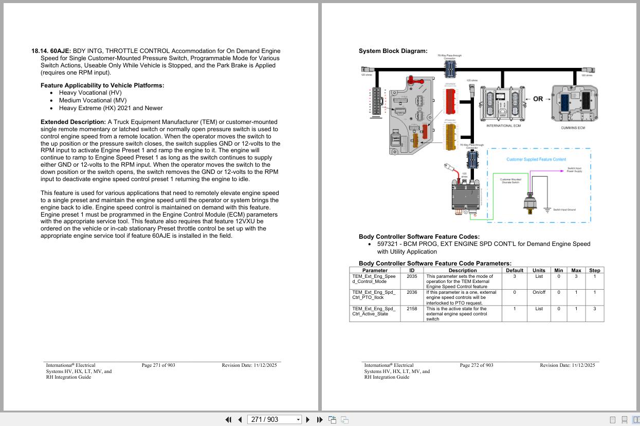
18.1. 12VGV: ACCESSORY WIRING, SPECIAL for Road Speed Wire Coiled Under Instrument Panel for
Customer Use, Unconditioned Manual Transmission Output Shaft Speed, Additional Body
Builder Signal Conditioning may be Required to Utilize Signal
18.2. 12VXT: THROTTLE, HAND CONTROL Engine Speed Control; Electronic, Stationary, Variable
Speed; Mounted on Steering Wheel
18.3. 12VXU: THROTTLE, HAND CONTROL Engine Speed Control for AESC; Electronic, Stationary
Pre-Set, Two Speed Settings; Mounted on Steering Wheel
18.4. 12VXV: THROTTLE, HAND CONTROL Engine Speed Control for AESC; Electronic, Mobile (Range
2 to 20-MPH), Variable Speed; Mounted on Steering Wheel.
18.5. 12VGV: ACCESSORY WIRING, SPECIAL for Road Speed Wire Coiled Under Instrument Panel for
Customer Use, Unconditioned Manual Transmission Output Shaft Speed, Additional Body
Builder Signal Conditioning may be Required to Utilize Signal
18.6. 12VYL: ACCESSORY WIRING, SPECIAL for Road Speed Wire Coiled Under Instrument Panel for
Customer Use.
18.7. 12VGA Post 2022 Model Year: ENGINE CONTROL, REMOTE MOUNTED for AESC, with S13
Engines
18.7.1. 12VGA Preset Set Speed – Wiring Diagram:
18.7.2. 12VGA Preset Resume Speed – Wiring Diagram:
18.7.3. 12VGA Preset Set Resume Speed – Wiring Diagram:
18.7.4. 12VGA Variable Switch Control – Wiring Diagram:
18.7.5. 12VGA Variable Pedal Control – Wiring Diagram:
18.7.6. 12VGA Aux Tachometer Output – Wiring Diagram:
18.7.7. 12VGA Aux Speedometer Output – Wiring Diagram:
18.7.8. 12VGA Engine Waring Lamp – Wiring Diagram:
18.8. 12VGA Pre 2022 Model Year A26: ENGINE CONTROL, REMOTE MOUNTED for AESC, for A26
Engines
18.8.1. 12VGA Preset Set Speed – Wiring Diagram:
18.8.2. 12VGA Preset Resume Speed – Wiring Diagram:
18.8.3. 12VGA Preset Set Resume Speed – Wiring Diagram:
18.8.4. 12VGA Variable Switch Control – Wiring Diagram:
18.8.5. 12VGA Variable Pedal Control – Wiring Diagram:
18.8.6. 12VGA Transfer Case Speed Disable – Wiring Diagram:
18.8.7. 12VGA Aux Tachometer Output – Wiring Diagram:
18.8.8. 12VGA Aux Speedometer Output – Wiring Diagram:
18.8.9. 12VGA Engine Waring Lamp – Wiring Diagram:
18.9. 12VGA Post 2021 Model Year A26: ENGINE CONTROL, REMOTE MOUNTED for AESC, for A26
Engines
18.9.1. 12VGA Preset Set Speed – Wiring Diagram:
18.9.2. 12VGA Preset Resume Speed – Wiring Diagram:
18.9.3. 12VGA Preset Set Resume Speed – Wiring Diagram:
18.9.4. 12VGA Variable Switch Control – Wiring Diagram:
18.9.5. 12VGA Variable Pedal Control – Wiring Diagram:
18.9.6. 12VGA Transfer Case (Split Shaft) Speed Disable – Wiring Diagram:
18.9.7. 12VGA Aux Tachometer Output – Wiring Diagram:
18.9.8. 12VGA Aux Speedometer Output – Wiring Diagram:
18.19. Datalink Control for Split Shaft Operation: J1939 DATALINK ENGINE CONTROL for International
A26 and S13 Engines - Fog, Plow, and Guide Post Accommodation Packages
19.1. 8585: TOGGLE SWITCH, AUXILIARY and Wiring; For Driving Lights or Fog Lights Mounted by
Customer.
19.2. 08THJ: AUXILIARY HARNESS 3.0’ for Auxiliary Front Headlights and Turn Signals for Front Plow
Applications
19.3. 08THV: DISCONNECT, FRONT HARNESS for Guide Post Lights; Connectors Located at Headlight
Connection, for Customer Installation
19.4. 08TNP: AUXILIARY HARNESS 5.0’ for Auxiliary Front Headlights and Turn Signals for Front Plow
Applications
19.5. 08WLM: FOG LIGHTS {Peterson} Amber, Halogen, Rectangular
19.6. 08WLN: FOG LIGHTS {Peterson} Clear, Halogen, Rectangular.
19.7. 08WPL: FOG LIGHTS (2) Amber, Oval, With H355W Halogen Bulb.
19.8. 08WPM: FOG LIGHTS (2) Clear, Oval, With H355W Halogen Bulb
19.9. 08XJG: FOG LIGHTS (2) Clear, Lens, Halogen, Rectangular, with White Light Source
19.10. 08XJH: FOG LIGHTS (2) Clear, Lens, LED, Rectangular, with White Light Source
19.11. 08XJJ: FOG LIGHTS (2) Selective Yellow, LED - Disable ABS/ATC for Rail Applications
20.1. Disabling ABS/ATC by Removing Power to Module
20.2. Disable ABS/ATC with Bendix ABS inputs: - Lift Axles
21.1. Lift Axle Control (Using Conventional Air Solenoid Module):
21.2. Lift Axles (Using ELAM):
21.3. Lift Axle Electronic Gauges: - Gauges and Fault Display
22.1. 16HGG: GAUGE, OIL TEMP, ENGINE
22.2. 16HGH: OIL TEMP GAUGE FOR AUTOMATIC TRANS
22.3. 16HGJ: GAUGE, OIL TEMP, MANUAL TRANSMISSION
22.4. 16HGL: GAUGE, OIL TEMP, REAR AXLE
22.5. 16HGN: GAUGE, AIR APPLICATION
22.6. 16HHT: GAUGE, Ammeter 150-Ampere (AMP)
22.7. 16HKT: IP CLUSTER DISPLAY DIAGNOSTICS — Display on board diagnostics of fault codes in
gauge cluster
22.8. 16HLR: VIRTUAL GA, OIL TEMP, Air Application Requires Premium Cluster
22.9. 16HLS: VIRTUAL GA, OIL TEMP, REAR AXLE Requires Premium Cluster
22.10. 16HLU: VIRTUAL GA, OIL TEMP, AUTO XMSN for Allison Transmission, Requires Premium
Cluster.
22.11. 16HLV: VIRTUAL GA, OIL TEMP, MANL XMSN for Manual Transmission, Requires Premium
Cluster.
22.12. 16HLW: VIRTUAL GAUGE, OIL TEMP, ENG Requires Premium Cluster. - In Cab Battery Feed Power Source
23.1. 8518: CIGAR LIGHTER Includes Ash Cup.
23.2. 8718: POWER SOURCE Cigar Type Receptacle without Plug and Cord.
23.3. 08WCK POWER SOURCE, TERMINAL TYPE 2-Post.
23.4. 08XHR POWER SOURCE, ADDITIONAL Auxiliary Power Outlet (APO) & USB Port, Located in the
Instrument Panel
23.5. 08XKR: POWER SOURCE, Two Auxiliary Power Outlets (APO) and Two USB Ports, Located in the
Instrument Panel - Indicator Lights and Alarms
24.1. 60AJC: BDY INTG, INDICATOR LIGHTS (2) One for Gate Open and One for Rear Alert, Includes
Audible Alarm, Programmable Mode for Various Switch Action (requires 2 Remote Power
Module (RPM) inputs).
24.2. 60AJD: BDY INTG, INDICATOR LIGHTS (2) One for Boom Out of Stow, One for Outriggers
Deployed, Includes Audible Alarm and Interlock to Parking Brake, Programmable Mode for
Various Switch Actions (requires 2 RPM inputs)
24.3. 60AJK: INDICATOR LIGHTS (2), One for Body Up, One for Gate Open, Includes Audible Alarm,
Programmable Mode for Various Switch Actions (Requires 2-RPM Inputs).
24.4. 60AKY: BDY INTG, DASH IND LT TRICOLOR (1) for Optional Usage Customer to Program.
24.5. 60AKZ: BDY INTG, DASH IND LT TRICOLOR (2) for Optional Usage Customer to Program
24.6. 60ALA: BDY INTG, DASH IND LT TRICOLOR (3) for Optional Usage Customer to Program
24.7. 60ALB: BDY INTG, DASH IND LT TRICOLOR (4) for Optional Usage Customer to Program
24.8. 60ALC: BDY INTG, DASH IND LT TRICOLOR (5) for Optional Usage Customer to Program.
24.9. 60ALD: BDY INTG, DASH IND LT TRICOLOR (6) for Optional Usage Customer to Program.
24.10. 60ALE: BDY INTG, DASH IND LT TRICOLOR (7) for Optional Usage Customer to Program
24.11. 60ALG: BDY INTG, DASH IND LT TRICOLOR (8) for Optional Usage Customer to Program.
24.12. 60ALH: BDY INTG, DASH IND LT TRICOLOR (9) for Optional Usage Customer to Program.
24.13. 60ALJ: BDY INTG, DASH IND LT TRICOLOR (10) for Optional Usage Customer to Program.
24.14. 60ALK: BDY INTG, DASH IND LT TRICOLOR (11) for Optional Usage Customer to Program
24.15. 60ALL: BDY INTG, DASH IND LT TRICOLOR (12) for Optional Usage Customer to Program. - Liftgate Accommodation Packages
25.1. 08VBA: POWER SOURCE, SPECIAL for Customer Installed Lift Gate; 200 Amp Max, Includes
00ga. Power Cable to End of Frame, Optional Power (PDM) for Power Source, Latched Switch
on Instrument Panel, with a Time Out Feature, Battery Discharge Protection, Controlling a Mag
Switch Which Provides Power
25.2. 08TWG: POWER SOURCE, SPECIAL {Erich Jaeger} Socket, Single Terminal, for Power Lift Gate
Feed, Battery Feed Thru 150 Amp Circuit Breaker, To Operate Lift Gate On Trailer, Includes a
15’ Power Cable Coiled In Cab
25.3. 08TWJ: POWER SOURCE, SPECIAL {Erich Jaeger} Socket, Dual Pole Terminal, for Power Lift
Gate Feed, Battery Feed Thru 150 Amp Circuit Breaker, To Operate Lift Gate On Trailer,
Includes a 15’ Coiled Dual Pole Power Cable Shipped in Cab
25.4. 08WCM: POWER SOURCE, Special Socket; Single Terminal, for Power Lift Gate Feed, Battery
Feed Thru 150-Amp Circuit Breaker, To Operate Lift Gate on Trailer, includes a 15-foot Power
Cable Coiled in Cab.
25.5. 08WJA: POWER SOURCE, SPECIAL for Customer Installed Lift Gate; 200 Amp Max, Includes
2ga. Power Cable to End of Frame, Latched Switch on Instrument Panel, with a Time Out
Feature, Battery Discharge Protection, Controlling a Mag Switch Which Provides Power
25.6. 08WJH: POWER SOURCE, SPECIAL – Special Socket; Dual Pole Terminal, for Power Lift Gate
Feed, Battery Feed Thru 150-Amp Circuit Breaker to Operate Lift Gate on Trailer.
25.7. 08WKP: POWER SOURCE, SPECIAL {Phillips} Socket, Dual Pole Terminal, for Power Lift Gate
Feed, Battery Feed Thru 150 Amp Circuit Breaker, To Operate Lift Gate On Trailer, Includes a
15’ Coiled Dual Pole Power Cable Shipped in Cab
25.8. 08WSS: POWER SOURCE, SPECIAL {Phillips} Socket, Dual Pole Terminal, for Power Lift Gate
Feed, Battery Feed Thru 150 Amp Circuit Breaker, To Operate Lift Gate On Trailer, includes a
Phillips Weather-Tite M2 12’ Straight Dual Pole Power Cable Shipped in Cab - Power Features using Remote Power Modules
26.1. 60ACE: BDY INTG, SWITCH DUAL OUTPUT 2-Position Latched Rocker, Backlit, with “ON”
Indicator Mounted on Dash, for 1; Auxiliary Load 40-AMP Maximum; Power Available Only in
“Ignition (IGN)” or “Accessory” Position; Controls Two Remote Power Modules (RPMs)
(requires two RPM outputs)
26.2. 60ACG: BDY INTG, SWITCH, INTERLOCKED 2-Position Latched Rocker, Backlit, with “ON”
Indicator Mounted on Dash for 1; Auxiliary Load 20-Ampere (AMP) Maximum; Output will
disengage when Vehicle Exceeds 30-MPH, Programmable; Power Available Only in “Ignition
(IGN)” or “Accessory” Position (requires one Remote Power Module (RPM) output).
26.3. 60ACH: BDY INTG, SWITCH, INTERLOCKED (2) 2-Position Latched Rockers, Backlit, with “ON”
Indicator Mtd on Dash, for 2; Auxiliary Load each 20-AMP Maximum; Outputs will Disengage
when Vehicle Exceeds 30-MPH, Programmable; Power Available Only in “IGN” or “Accessory”
Position (requires two RPM outputs).
26.4. 60ACS: BDY INTG, SWITCH MOMNTRY 3POS Rocker, Backlit, with “ON” Indicator Mounted on
Dash, Latching Software, for 1 Auxiliary Load 20-amp. Maximum; Power Available Only in
“Ignition” or “Accessory” Position, Output Also Controlled by a Customer Remote Mounted
Switch (requires 1 Remote Power Module input and 1output).
26.5. 60ACT: BDY INTG, SWITCH MOMNTRY 3POS Rocker, Backlit, with “ON” Indicator Mounted on
Dash, Latching Software, for 2; Auxiliary Load 20-AMP Maximum; Power Available Only in
“IGN” or “Accessory” Position, Output Also Controlled by a Customer Remote-Mounted Switch
(requires two RPM inputs and two outputs).
26.6. 60ACU: BDY INTG, SWITCH MOMNTRY 3-POS (3) Rocker, Backlit, with “ON” Indicator Mounted
on Dash, Latching Software, for 3; Auxiliary Load 20-AMP Maximum; Power Available Only in
“IGN” or “Accessory” Position, Output Also Controlled by a Customer Remote-Mounted Switch
(requires three RPM inputs and three outputs).
26.7. 60AJL: BDY INTG, REMOTE POWER MODULE Mounted Inside Cab; Up to 6-Outputs & 6 Inputs,
Max. 20-AMP per Channel, Max. 80-AMP Total; (Includes 1-Switch Pack with Latched
Switches).
26.8. 60AJM: BDY INTG, REMOTE POWER MODULE (2) Mounted Inside Cab; Up to 6- Outputs & 6-
Inputs each, Max. 20-AMP per Channel, Max. 80-AMP Total; (Includes Switch Packs with
Latched Switches) - Power Window, Locks, Remote Keyless Entry
27.1. 16VCN: KEYLESS ENTRY SYSTEM REMOTE with Panic and Auxiliary Work Light Function,
Includes One Key Fob (Transmitter)
27.2. 16VCP: KEYLESS ENTRY SYSTEM REMOTE with Panic and Horn Beep Lock Confirmation, with
Auxiliary Button for Work Light, Includes One Key Fob (Transmitter)
27.3. 16WJU: WINDOW, POWER (2-Door) and Power Locks, Left and Right Doors.
27.4. 16WJV: WINDOW, POWER (4-Door) and Power Door Locks, Front and Rear Doors, Left and Right. .
27.5. 16WKZ: KEYLESS ENTRY SYSTEM REMOTE with Panic and Auxiliary Buttons, Includes One Key
Fob (Transmitter). - Productivity Features
28.1. 08THN: TURN SIGNAL SWITCH with Hazard Flasher Overrides Brake, to be done With
Programming System Controller
28.2. 08WXB: HEADLIGHT WARNING BUZZER Sounds When Head Light Switch is on, and Ignition
Switch is in “Off” Position.
28.3. 08WXD: ALARM, PARKING BRAKE Electric Horn Sounds in Repetitive Manner when Vehicle Park
Brake is “NOT” Set, With Ignition (IGN) “OFF” and any Door Open.
28.4. 16HCK: SEATBELT WARNING PREWIRE for 1 to 3 Belts.
28.5. 16HCL: SEATBELT WARNING PREWIRE for 4 to 6-Belts - Remote Power Modules
29.1. 08SAJ: SWITCH, BODY CIRCUITS, MID for Body Builder; 12-Momentary Switches in IP, With Two
Power Modules with Six Channels, 20-AMP Max. per Channel, 80-AMP Max. Output, Switch
Control Power Modules through Multiplex Wiring, Mounted on Battery Box, BOC.
29.2. 08VZR: SWITCH, BODY CIRCUITS, MID for Bodybuilder, 6-Switches in Instrument Panel; One
Power Module with 6 Channels, 20-Amp Max. Per Channel, 80 Amp Max Output, Switches
Control Power Module Through Multiplex Wiring, Mounted in Cab Behind Driver Seat
29.3. 08VZS: SWITCH, BODY CIRCUITS, MID for Bodybuilder, 12-Switches in Instrument Panel; Two
Power Modules with 6 Channels, 20-Amp Max. Per Channel, 80-Amp Max Output, Switches
Control Power Module Through Multiplex Wiring, Mounted in Cab Behind Driver Seat
29.4. 08WSK: SWITCH, BODY CIRCUITS, REAR for Body Builder; With Six Momentary Switches in
Instrument Panel (IP); One Power Module, With Six Channels, 20-Ampere (AMP) per Channel
and 80 AMP Max. Output, Switches Control the Power Modules through Multiplex Wiring,
Mounted at Rear on Frame.
29.5. 08WSM: SWITCH, BODY CIRCUITS, MID for Body Builder, With Six Momentary Switches in IP;
One Power Module with Six Channel, 20-AMP Max. per Channel and 80 AMP Max. Output,
Switches Control the Power Module through Multiplex Wiring, Mounted Battery Box, Back of
Cab (BOC).
29.6. 60AAA: BDY INTG, RPM Mounted Under Cab; Up to Six Outputs and Six Inputs, Max. 20-AMP per
Channel, Max. 80-AMP Total (Includes One Switch Pack with Latched Switches) Mounted on
Battery Box, BOC
29.7. 60AAB: BDY INTG, RPM (2) Mounted Under Cab; Up to Six Outputs and Six Inputs Each, Max. 20
AMP per Channel, Max. 80 AMP Total per Power Module (Includes Switch Packs with Latched
Switches) Mounted on Battery Box, BOC.
29.8. 60AAD: BDY INTG, RPM (2) {SPECIAL} Mounted Under Cab or on Battery Box; Max. 20-AMP per
Channel, Max. 80-AMP Total per Power Module; Includes One Module with Switch Pack
Containing Six Latched Switches and One Module with Hardware Only
29.9. 60AAG: BDY INTG, RPM Mounted Inside Cab behind Driver Seat; Max. 20-AMP per Channel, Max.
80-AMP Total; Includes One Module with Switch Pack Containing Latched Switches.
29.10. 60AAH: BDY INTG, RPM (2) Mounted Inside Cab behind Driver Seat; Max. 20-AMP per Channel,
Max. 80-AMP Total; Includes Two Modules with 2-Switch Packs Containing Latched Switches..
29.11. 60AAJ: BDY INTG, RPM (3) Mounted Inside Cab behind Driver Seat; Max. 20-AMP per Channel,
Max. 80-AMP Total; Includes Three Modules with 3-Switch Packs Containing Latched
Switches.
29.12. 60AAK: BDY INTG, RPM (2) {SPECIAL} Mounted Inside Cab behind Driver Seat; Max. 20-AMP
per Channel, Max. 80-AMP Total; Includes One Module with Switch Pack Containing Six
Latched Switches and One Module with Hardware Only.
29.13. 60AAL: BDY INTG, RPM {SPECIAL} Mounted Inside Cab behind Driver Seat; Max. 20-AMP per
Channel, Max. 80-AMP Total; Includes Three Modules with Hardware Only.
29.14. 60AAM: BDY INTG, RPM AUX Mounted on the Driver’s Side Frame Rail at Rear of Frame; Up to
6-Outputs and 6-Inputs, Max. 20-AMP per Channel, Max. 80-AMP Total.
29.15. 60AAN: BDY INTG, RPM AUX Mounted Back of Cab; Up to 6-Outputs and Inputs, Max. 20-AMP
per Channel, Max. 80-AMP Total - Remote Start/Stop Features
30.1. 08XRX: ENGINE SHUTDOWN CUSTOMER INSTALL SWITCH.
30.2. 60ABC: BDY INTG, REMOTE START/STOP to Start and Stop Vehicle Engine.
30.3. 60ABD: BDY INTG, REMOTE START/STOP To Start and Stop Vehicle Engine, Will Start
Emergency Pump Motor, Programmable Time Intervals - Secondary Road Speed Limit
31.1. Datalink Control for Secondary Road Speed Limit Control: J1939 DATALINK ENGINE CONTROL
for Navistar A26 Engines - Standard electrical Offerings
32.1. 08WRB: HEADLIGHTS ON W/WIPERS Headlights Will Automatically Turn on if Windshield Wipers
are turned on. There are two functions, Lights on With Wipers (LOWW) and Day Time Running
Lights (DTRL), available with this sales code. - Theft Deterrent
33.1. 60ACX: BODY INTG, THEFT DETERRENT SYS Includes one (1) Switch Pack of Six Switches. - PTO (Power Take OFF) and PTO Hour Meter (Not T14 Transmission)
34.1. 13TLR: PTO, SPLIT SHAFT {NAMCO Model 463-A-SPSSXS-Y-362} Power Tower Above Rail
Provides a Power Source for Customer Equipment, PTO Ratio 1:1 w/Driveline; Upper Front
PTO Output Decouplable; Upper Rear PTO Output Non-Decouplable; Case Hardened Helical
Gears; Lube Pump, Requires Customer Mounted External Cooler System 509 BTU/Min
Minimum Capacity
34.2. 13WDN: PTO CONTROL, DASH MOUNTED for Customer Provided PTO; Includes 2-Independent
Illuminated Switches, 2-Electric/Air Solenoids, Piping and Wiring
34.3. 13XAA : PTO CONTROL, DASH MOUNTED for Customer Provided PTO; Includes Switch,
Electric/Air Solenoid, Piping and Wiring
34.3.1. 13XAA PTO CONTROL, DASH MOUNTED for Customer Provided PTO; Includes Switch,
Electric/Air Solenoid, Piping and Wiring
34.3.2. 13XAA PTO CONTROL, DASH MOUNTED for Customer Provided PTO; Includes 1- Illuminated
Switch, 1-Electric/Air Solenoid, Piping and Wiring.
34.4. 13XAB: PTO CONTROL, DASH MOUNTED For Customer Provided PTO on Transfer Case;
Includes Switch, Electric/Air Solenoid, Piping and Wiring
34.5. 16WLM: HOUR METER, PTO for Customer Provided PTO; Indicator Light and Hour meter in
Gauge Cluster Includes Return Wire for PTO Feedback Switch.
34.6. 60ABA: BDY INTG, PTO ACCOMMODATION for Monitoring Cable Shift Engaged PTO, With
Indicator Light and Audible Alarm in Gauge Cluster (requires one Remote Power Module
(RPM) input)
34.7. 60ABB: BDY INTG, PTO ACCOMMODATION for Muncie Lectra-Shift PTO Engagement and
Disengagement, With Switch Mounted on Dash; Includes Indicator Light and Audible Alarm in
Gauge Cluster (requires one RPM input and one output).
34.8. 60ABE: BDY INTG, PTO ACCOMMODATION for Electric over Hydraulic PTO, With Switch
Mounted on Dash, Includes Audible Alarm, and Indicator Light in Gauge Cluster (Requires one
RPM input and one output). This feature does Not Include Solenoids.
34.9. 60ABK: BDY INTG, PTO ACCOMMODATION. Accommodation for Electric over Air, Non-Clutched
PTO Engagement and Disengagement does not Include Air Solenoid, With Switch Mounted on
Dash, Includes Audible Alarm, and Indicator Light in Gauge Cluster (requires one RPM input
and one output)
34.10. 60ABL: BDY INTG, PTO ACCOMMODATION. Accommodation for Electric over Air, Clutched PTO
Engagement and Disengagement, does not Include Air Solenoid, With Switch Mounted on
Dash, Includes Audible Alarm, and Indicator Light in Gauge Cluster (requires one RPM input
and one output)
34.11. 60AKG: BDY INTG, PTO ACCOMMODATION for (3) Latched Rocker Switches, (1) PTO Switch,
(2) Generic Switches to Control (3) 30-amp relays, with Programmable Interlocks, for Body
Builder Hook up in the Engine Compartment Left Side, Recommended for Automatic
Transmissions - International® T14 Transmission Features
35.1. PTO With International® T14 Transmission with Transmission Mounted PTOs
35.2. 60AME T14 Split Shaft PTO Customer provided Transfer Case
35.3. 13WME MANEUVERING MODE
13WME MANEUVERING MODE Maintains Low Speed Throttle Control to Reduce Harsh Driveline
Engagement/Disengagement, Enables Slow & Steady Trailer Hook up, Docking & Tight Space
Driving, Includes Switch, for T14 Transmission.
35.4. 13WMU/13WMV T14 Neutral Force/Hold
35.5. 13WMW T14 Paver Assist
35.6. 60AMB T14 PTO Inhibit
35.7. 60AMC T14 PTO Accommodation from 3rd Party Controller
35.8. 60AMD Dual Shifter for T14 – Under Development
35.9. 60AMG T14 Transmission Range Limiter - Eaton® Transmissions Integration Features
36.1. Eaton® Ultrashift™ Transmission PTO Feedback
36.2. Eaton® Procision™ Transmission
13WEP: WIRING, TRANS, BODY BUILDER Installed Wiring and Connector for Transmission/PTO
Controls, for Eaton® Procision™ Transmission
13WEW: WIRING, TRANSMISSION Installed Wiring and Connector for Transmission/PTO Controls, for
Eaton® Endurant™ Transmission.
36.3. Eaton® Endurant™ Transmission Split-Shaft Feature Codes
Refer to Endurant XD Series PTO Installation and Body Integration Guide TRIG2620 EN-US
36.4. 13WMJ ROCK-FREE OPERATIONAL MODE Eaton® Endurant™ Rock-Free Feature Code
Refer to Endurant XD Series PTO Installation and Body Integration Guide TRIG2620 EN-US - Allison 1000 and 2000 Transmission Spare Input/Output (I/O) and Sales Codes
37.1. 13WDH Description: WIRING, TRANS BODY BUILDER Installed Wiring for Transmission/PTO
Controls, for Allison 2000, 2100, 2200, 2400, 2500 Series Transmission Only
37.2. 13XAC: ALLISON SPARE INPUT/OUTPUT for Rugged Duty Series (RDS), General Purpose
Trucks, Package Number 354, Modified for Single Input Auto Neutral - Allison 3000 and 4000 Transmission Auto Neutral
38.1. 13AAZ: AUTOMATIC NEUTRAL Allison 3000 & 4000 Series Transmission Shifts to Neutral When
Parking Brake is Engaged
38.2. 13WEH: AUTOMATIC NEUTRAL Allison WT Transmission Shifts to Neutral When Parking Brake is
Engaged and Remains in Neutral When Parking Brake is Disengaged, without On/Off Switch
38.3. 13WUA: ALLISON NEUTRAL Allison WT Transmission Shifts to Neutral When Parking Brake is
Engaged and Remains on Neutral When Park Brake is Disengaged - Allison 3000 and 4000 Transmission Spare Input/Output (I/O) and Sales Codes
39.1. 13WUB: ALLISON SPARE INPUT/OUTPUT for Highway Series (HS); General Purpose Trucks.
Package number 223
39.2. 13WUC: ALLISON SPARE INPUT/OUTPUT for Rugged Duty Series (RDS); General Purpose
Trucks, Construction.
39.3. 13WUD: ALLISON SPARE INPUT/OUTPUT for Emergency Vehicle Series (EVS); Rescue,
Ambulance
39.4. 13WUE: ALLISON SPARE INPUT/OUTPUT for Emergency Vehicle Series (EVS); Fire/Pumper,
Tank, Aerial/Ladder
39.5. 13WUH: ALLISON SPARE INPUT/OUTPUT for Rugged Duty Series (RDS); Airport Refueler,
Sewer Evac
39.6. 13WUJ: ALLISON SPARE INPUT/OUTPUT for Rugged Duty Series (RDS); Front Loaders, Rear
Loaders, Recycling/Packer Trucks.
39.7. 13WUK: ALLISON SPARE INPUT/OUTPUT for Rugged Duty Series (RDS); Side Loaders.
39.8. 13WUL: ALLISON SPARE INPUT/OUTPUT for Rugged Duty Series (RDS); Street Sweeper.
39.9. 13WUN: ALLISON SPARE INPUT/OUTPUT for Motorhome Series (MH), Package Number 226
39.10. 13WUR: ALLISON SPARE INPUT/OUTPUT for Rugged Duty Series (RDS); Dump/Construction
with Two-Speed Axle or Auxiliary Transmission, Package Number 146
39.11. 13WUS: ALLISON SPARE INPUT/OUTPUT for Rugged Duty Series (RDS); General Purpose
Trucks Modified for Single Input Auto Neutral
39.12. 13WUT: ALLISON SPARE INPUT/OUTPUT for Emergency Vehicle Series (EVS); Without Split
Shaft PTO.
39.13. 13WUV: ALLISON SPARE INPUT/OUTPUT for Highway Series (HS); General Purpose Trucks
Modified for Single Input Auto Neutral.
39.14. 13WUY: ALLISON SPARE INPUT/OUTPUT for Oil Field Series (OFS), Package Number 193
39.15. 13WUZ: ALLISON SPARE INPUT/OUTPUT for Emergency Vehicle Series (EVS), Fire/Pumper,
Tank, Aerial/Ladder, Package Number 198, Includes J1939 Based Auto Neutral.
39.16. 13WVA: ALLISON SPARE INPUT/OUTPUT for Emergency Vehicle Series (EVS), 303/360
Includes J1939 Based Auto Neutral; Fire/Pumper, Tank, Aerial/Ladder
39.17. 13WVB: ALLISON SPARE INPUT/OUTPUT for Emergency Vehicle Series (EVS), Rescue,
Ambulance, Package Number 170, Includes J1939 Based Auto Neutral.
39.18. 13WVX: ALLISON SPARE INPUT/OUTPUT for Rugged Duty Series (RDS), On/Off Highway,
Package Number 235 - FEPTO/REPTO
40.1. Non S13 Integrated FEPTO/REPTO
40.2. S13 Integrated FEPTO/REPTO - Auxiliary Transmission
- Work Light and Outside Cab Power Features
42.1. 08TMH: SWITCH, AUXILIARY Accessory Control; for Wiring in Roof, With Maximum of 20 AMP
Load with Switches in the Instrument Panel.
42.2. 08WEX: AUXILIARY HARNESS for Auxiliary Power Source; 30-Amp, Key Switched, 2-Pin
Connector, Located on Floor Between Seats.
42.3. 08WGV: WORK LIGHT WIRING for (2) Customer Installed Work Lights, Mounted on Top Rear
Corners of Cab, with Switch on Dash, Switch Will Also Activate Standard Work Light
42.4. 08WJE: WORK LIGHT WIRING for (2) Customer Installed Work Lights, Mounted on Top Rear
Corners of Cab, with Switch on Dash, Switch Will Also Activate Standard Work Light and
Backup Lights when Vehicle is in Reverse or Park Brake Applied.
42.5. 08WJZ: WORKLIGHT ON W/BACKUP Work Lights will Activate when Vehicle is in Reverse
42.6. 08WTT: SWITCH, TOGGLE, FOR WORK LIGHT Lighted; on Instrument Panel and Wiring Effects
for Customer Furnished End of Frame Light
42.7. 08XBK: SWITCH, AUXILIARY Switch 40-AMP Circuit for Customer Use; Includes Wiring
Connection in the engine compartment near the mega-fuse
42.8. 08XBM: TOGGLE SWITCH, AUXILIARY (1) with One 30-Amp Circuit Breaker
42.9. 08XBN: TOGGLE SWITCH, AUXILIARY (2) with Two 30-Amp Circuit Breakers.
42.10. 08WAA: WORK LIGHT (LED); Pedestal Mounted with Switch on Instrument Panel (Truck Lite 81
Series).
42.11. 08WJZ: WORKLIGHT ON W/BACKUP Work Lights will Activate when Vehicle is in Reverse
42.12. 08WTT: SWITCH, TOGGLE, FOR WORK LIGHT Lighted; on Instrument Panel and Wiring Effects
for Customer Furnished End of Frame Light
42.13. 08WEX: AUXILIARY HARNESS for Auxiliary Power Source; 30-Amp, Key Switched, 2-Pin
Connector, Located on Floor Between Seats.
42.14. 08WLL: WORK LIGHT; Pedestal Mounted with Switch on Instrument Panel (Truck Lite 81 Series).
42.15. 08WMA: SWITCH, TOGGLE, FOR WORK LIGHT Lighted; on Instrument Panel and Wiring Effects
for Customer Furnished Back of Cab Light
42.16. 08WXN: WORK LIGHT (2) (Grote) 60 Series, Mounted Under Hood One Each Side.
42.17. 08XBK: SWITCH, AUXILIARY Switch 40-AMP Circuit for Customer Use; Includes Wiring
Connection in the engine compartment near the mega-fuse - Appendix – General Electrical Section:
43.1. “Red Gel Coating” Removal from Starter Studs and Electrical Connections
43.2. Connecting to 12 Volt Circuits
43.3. Recommended Circuit Protection
43.4. Color Code System for International® Truck Wiring:
43.5. Electrical Components Commonly Used by Equipment Installers:
43.6. Suppression
43.7. Welding Information
43.8. Routing Guidelines
43.9. Using Additional Batteries on a Vehicle.
43.10. Wire Splicing and Termination – Standard Terminals and Splices:
43.11. HIGH VOLTAGE CIRCUITS (GREATER THAN 50 VOLTS) ON INTERNATIONAL® TRUCKS AND
BUSES:
Related Products
-
International Truck eMV Series Body Integration Quick Reference Guide
0 out of 530 USDSize: 5.95 MBFormat: PDFLanguage: EnglishBrand:Type of Machine: TruckType of Manual: Quick Reference GuideModel: International eMV Series Body Integration TruckPublication Date: 2022Number of Pages: 46 Pages
REALEASE :
REALEASE :
-
International Truck OnCommand Service Manual Diagrams PDF DVD
0 out of 5International Truck OnCommand 2.13 GB PDF Service Manual & DiagramsSize: 2,13GbLanguages: EnglishFormat: PDFBrand: International TruckTypes of Vehicle: TruckTypes of Manuals: Service Manual & DiagramsQuantity of CD: 1 DVDOS: All Window200Original price was: 200.60Current price is: 60. USDHot-70%
REALEASE :
14.04.2022
REALEASE :
14.04.2022
-
International Truck TC Commercial Bus Body Builder Book PBB-43200 2022
0 out of 530 USDSize: 4.95 MBFormat: PDFLanguage: EnglishBrand:Type of Machine: TruckType of Manual: Body Builder BookModel: International TC Commercial Bus TruckPart Number: PBB-43200Publication Date: 2022Number of Pages: 130 Pages
REALEASE :
REALEASE :
-
International Truck eMV Series Electrical Systems Integration Guide 2025
0 out of 550 USDSize: 7.53 MBFormat: PDFLanguage: EnglishBrand:Type of Machine: TruckType of Manual: Electrical Systems Integration GuideModel: International eMV Series TruckPublication Date: 2025Number of Pages: 179 Pages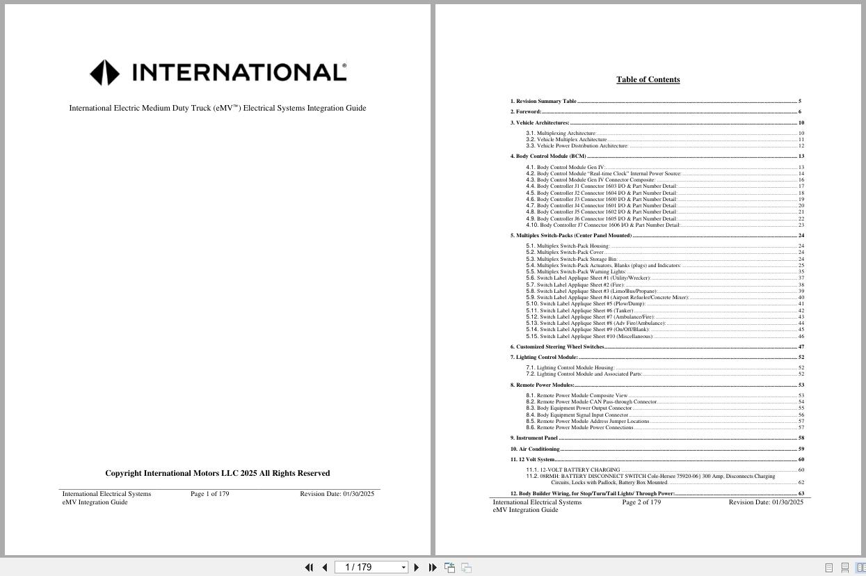
REALEASE :
REALEASE :
-
International Truck PayStar 5900 Electrical Diagram 0000002441 2021
0 out of 530 USDSize: 12.49 MBFormat: PDFLanguage: EnglishBrand:Type of Machine: TruckType of Manual: Electrical Diagram, Circuit DiagramModel: International PayStar 5900 TruckEngine Family: MaxxForce 11/13, 15L, N13 or ISX15 Engines with SCRPart Number: 0000002441 (Supersedes S08352)Publication Date: 2021Number of Pages: 348 Pages
REALEASE :
REALEASE :
-
International Truck MV Series TC Bus Interactive Schematics 0000018824 2021
0 out of 530 USDSize: 107.19 MBFormat: PDFLanguage: EnglishBrand:Type of Machine: TruckType of Manual: Interactive SchematicsModel: International MV Series TC Bus TruckBuilt: 1/1/2018 To 12/10/2021Built: 2018 – 2021Part Number: 0000018824Publication Date: 2021Number of Pages: 2394 Pages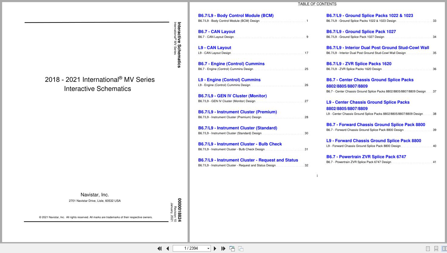
REALEASE :
REALEASE :
-
International Truck eMV Series Interactive Schematics 0000018831 2025
0 out of 550 USDSize: 22.29 MBFormat: PDFLanguage: EnglishBrand:Type of Machine: TruckType of Manual: Interactive SchematicsModel: International eMV Series TruckBuilt: 8/3/2021 To 12/31/2025Part Number: 0000018831Publication Date: 2025Number of Pages: 813 Pages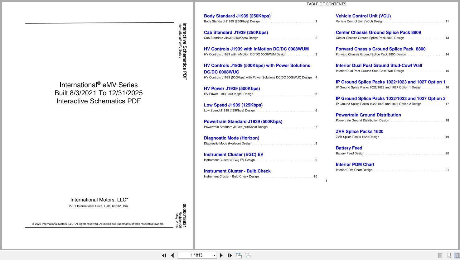
REALEASE :
REALEASE :
-
International Truck PayStar 5500i to 9900i Series Electrical Diagram 0000011981 2015
0 out of 530 USDSize: 24.27 MBFormat: PDFLanguage: EnglishBrand:Type of Machine: TruckType of Manual: Electrical Diagram, Circuit DiagramModel: International PayStar 5500i Series, 5600i Series, 5900i Series, 9200i Series, 9900i Series – ChassisBuilt: March 1, 2007 and AfterPart Number: 0000011981 (Supersedes S08326)Publication Date: 2015Number of Pages: 450 Pages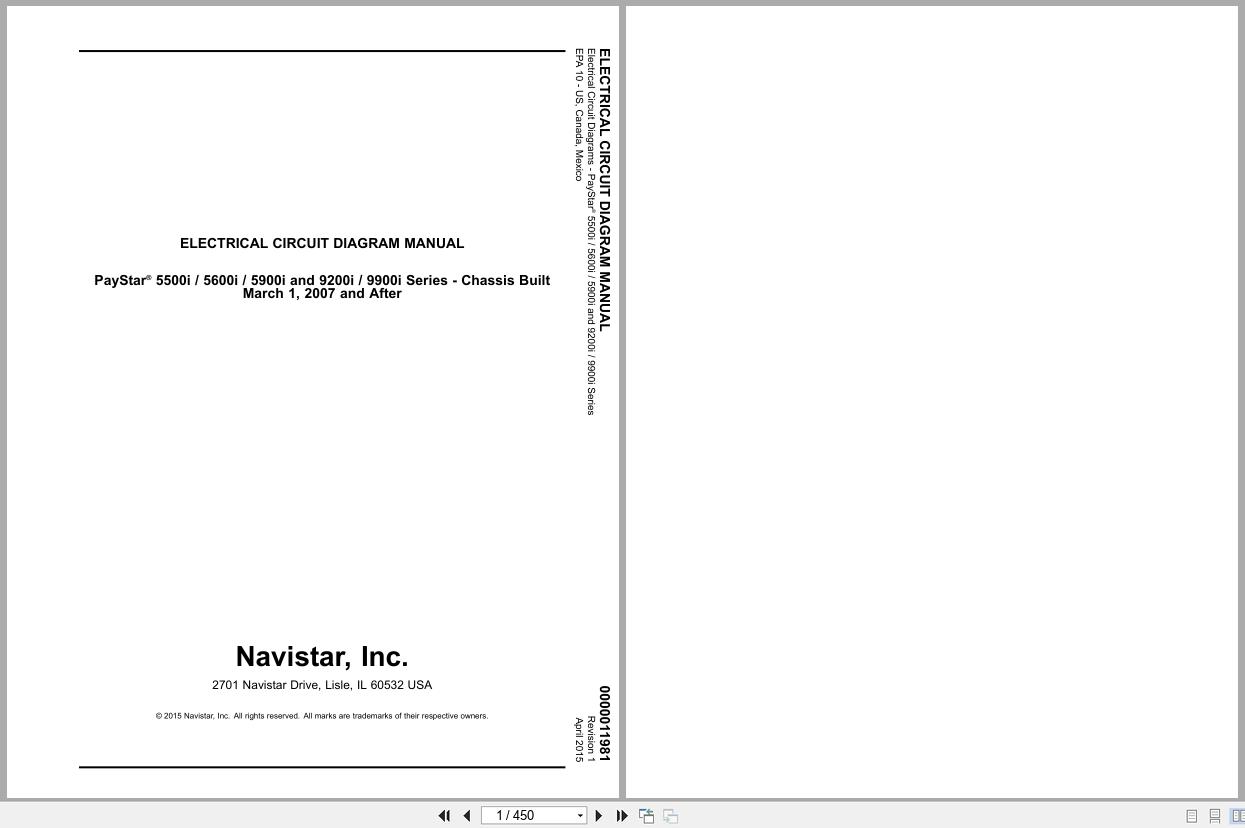
REALEASE :
REALEASE :