
0 ITEMSVIEW CART

✓
Expert Support
✓
Full Speed
✓
100% Working
John Deere 8225R 8245R 8270R 8295R 8320R 8345R Tractors Diagnostic Manual TM104219
Format: PDF
Language: English
Brand: John Deere
Type Of Manual: Diagnostic Manual
Type of Machine: Tractor
Model: John Deere 8225R 8245R 8270R 8295R 8320R 8345R
Parts Number: TM104219
200 USD
- Description
Description
Contents:
Introduction
Foreword
General Information
Safety
General References
Diagnostic Trouble Codes
ACU Code Diagnostics
ASU Code Diagnostics
ATC Code Diagnostics
BRC Code Diagnostics
CAB Code Diagnostics
CCU Code Diagnostics
CLC Code Diagnostics
CSM Code Diagnostics
ECU Code Diagnostics
HCC Code Diagnostics
HV1 Code Diagnostics
PDU Code Diagnostics
PTI Code Diagnostics
PTP Code Diagnostics
SCC Code Diagnostics
SFA Code Diagnostics
SSU Code Diagnostics
SV1 Code Diagnostics
SV2 Code Diagnostics
SV3 Code Diagnostics
SV4 Code Diagnostics
SV5 Code Diagnostics
SV6 Code Diagnostics
SV7 Code Diagnostics
TEC Code Diagnostics
VLC Code Diagnostics
VTI Code Diagnostics
System Diagnosis
Electrical system
Control Units
PowerShift Transmission
AutoPowr / IVT Transmission
Drive Systems
Steering Brakes
Hydraulics
Operator`s Station
Engines
Test Adjustments
Theory of Operation
Fuel Air
Theory of Operation
Electrical System
Load Center Fuses Relays Ground Points
Operational Checks
Functional Schematics Components Reference Lists
Connector Information
Harness Information
SE01 – Power Supply Starting Charging
SE02 – Standard Seat
SE03 – Manual A/C Automatic Temperature Control ATC
SE04 – Remote Mirror Option
SE05 – Radio Dome Lamp Steering Column Module
SE06 – CLC – Cab Load Center Control Unit Functions
SE06A – SE06A – CLC – Cab Load Center Control Unit Functions
SE06B – SE06B – CLC – North American Lighting Functions
SE06C – SE06C – CLC – European Lighting Functions
SE07 – Accessory Connectors
SE08 – Controller Area Network CAN Termination
SE09 – PDU/VTI/VTV/CSM-Cab Display Switch Module Functions
SE10 – CAB/ASU – Cab Control Unit Functions
SE10A – SE10A – CAB – CAB Control Unit Functions
SE10B – SE10B – ASU – ActiveSeat Control Unit Functions
SE11 – VLC/CCU/PTI/PTP – Vehicle Control Unit Functions
SE11A – SE11A – CCU – Chassis Control Unit Functions
SE11B – SE11B – VLC – Vehicle Load Center Control Unit Functions
SE11C – SE11C – PTI – AutoPowr / IVTIVT is a trademark of Deere & Company Transmission Control Unit Functions
SE11D – SE11D – PTP – Power Shift Transmission Control Unit Functions
SE13 – ACU – Armrest Control Unit Functions
SE14 – SCC/HCC/SFA/BRC – Deluxe Hydraulic Control Unit Functions
SE14A – SE14A – SCC – SCV Control Unit Functions
SE14B – SE14B – HCC – Hitch Control Unit Functions
SE14C – SE14C – BRC – Brake Control Unit Functions
SE14D – SE14D – SFA – Suspension Control Unit Functions
SE16 – ECU Level 14
SE17 – JDLink
SE18 – Greenstar Display
SE20 – SSU Steering System Unit
Control Units
General References
ACU
ASU
ATC
BRC
CAB
CCU
CLC
CSM
ECU
HCC
HV1
PDU
PTI
PTP
SCC
SFA
SSU
SV1-SV7
TEC/TEI
VLC
VTI
PowerShift Transmission
Preliminary Operational Checks
Tests Adjustments
Theory of Operation
Schematics Diagrams
AutoPowr / IVT Transmission
Preliminary Operational Checks
Tests Adjustments
Theory of Operation
Schematics Diagrams
Axles Differential Lock
Preliminary Operational Checks
Theory of Operation
Schematics Diagrams
MFWD
Preliminary Operational Checks
Tests Adjustments
Theory of Operation
Schematics Diagrams
Power Take-Off
Preliminary Operational Checks
Tests Adjustments
Theory of Operation
Schematics Diagrams
Suspended Front Axle
Preliminary Operational Checks
Tests Adjustments
Theory of Operation
Schematics Diagrams
Brakes
Preliminary Operational Checks
Test Adjustments
Theory of Operation
Schematics Diagrams
Steering
Preliminary Operational Checks
Test Adjustments
Theory of Operation
Schematics Diagrams
Hydraulics
Preliminary Operational Checks
Tests Adjustments
Theory of Operation
Schematics Diagrams
Air Conditioning
Preliminary Operational Checks
Theory of Operation
Schematics Diagrams
Seat
Preliminary Operational Checks
Tests Adjustments
Theory of Operation
Schematics Diagrams
Service Tools Installing Test Equipment
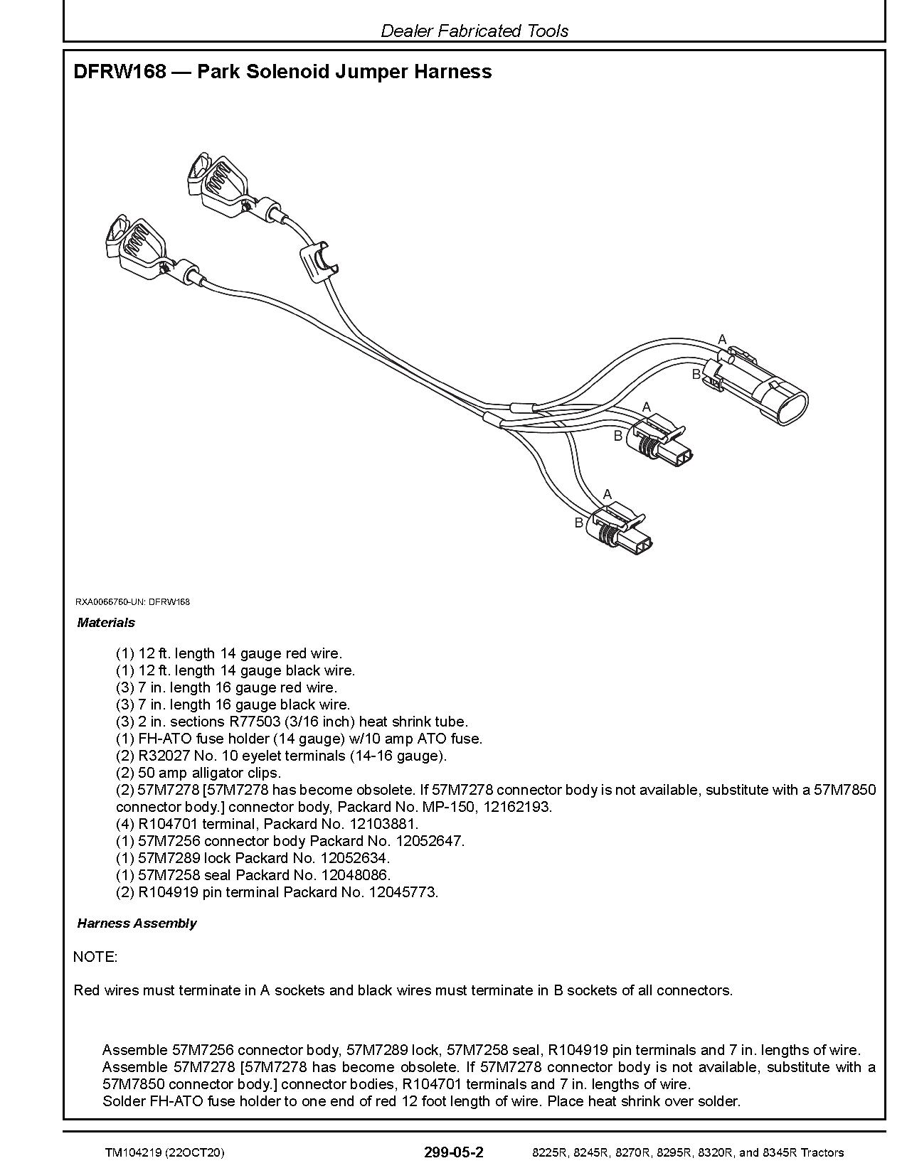
Dealer Fabricated Tools
Service Tools Kits
PowerShift Transmission-Install Test Equipment
AutoPowr / IVT Transmission-Install Test Equipment
Drive Systems-Install Test Equipment
Steering Brakes-Install Test Equipment
Hydraulics Install Test Equipment
Operator`s Station – Install Test Equipment
Section 256A
Section 256B
Section 256C
Section 256D
Section 260A
Section 260B
Section 290A
Section 290B
Related Products
-
John Deere Agricultural 25.1GB PDF Technical Manual Service Manual DVD
Original price was: 800.440Current price is: 440. USDJohn Deere Agricultural 25.1GB PDF Technical Manual Service Manual DVDSize: 25.1 Gb (PDF Files)Type of manual: Technical Manual Service ManualType of machine: John Deere AgricultureLanguage: English, German, Spanish, French, Lettisch, Tschechisch, Schwedish, Portuguese, Czech, Hungarian, Swedish, Dutch, Danish, BulgarischFormat: PDFBrand: John Deere, Hagie, Macdone, Rework, Roberine, DanfossOS: All WindowAmount of DVD: 1 DVDType of document: Technical Manual Service ManualHigh-Speed Link DownloadHot-45%
REALEASE :
12.21.2021
REALEASE :
12.21.2021
-
John Deere Lawn and Garden Full Model List Service Repair Diagnostic Operator Technical Manual
USDLet’s check the model’s list below. (You can use ctrl + F for the search Function)Let me know the models that you want through these email admin@autoepcservice.com or autoepcservice@gmail.comThen I will show you my price.High-Speed Link DownloadREALEASE :
13.05.2022
-
John Deere Tractor Full Model List Service Repair Diagnostic Operator Technical Manual
USDLet’s check the model’s list below. (You can use ctrl + F for the search Function)Let me know the models that you want through these email admin@autoepcservice.com or autoepcservice@gmail.comThen I will show you my price.High-Speed Link DownloadREALEASE :
13.05.2022
-
John Deere Tractor 15.8 GB PDF Operator’s Manual Updated 2021
Original price was: 300.170Current price is: 170. USDJohn Deere Tractor 15.8 Gb PDF Operation Manual Updated 2021Size: 15.8 GB (PDF Files)Language: EnglishType of manual: Operator’s ManualType of machine: John Deere Tractor AgriculturalFormat: PDFBrand: John DeereOS: All WindowAmount of DVD: 1 DVD_02High-Speed Link DownloadHot-43%
REALEASE :
14.04.2022
REALEASE :
14.04.2022
-
John Deere Service Manual PDF Collection 1.55 GB
Original price was: 300.180Current price is: 180. USDThis is a service information package, you will need to use this to repair a vehicleHot-40%
REALEASE :
REALEASE :
-
John Deere Agricultural Full Model List Service Repair Diagnostic Operator Technical Manual
USDLet’s check the model’s list below. (You can use ctrl + F for the search Function)Let me know the models that you want through these email admin@autoepcservice.com or autoepcservice@gmail.comThen I will show you my price.High-Speed Link DownloadREALEASE :
13.05.2022
-
JCB Diagnostic Tool SISU Power WinEEM4 Service Tool 2.7.2
Original price was: 200.100Current price is: 100. USDThis is a diagnostic program. You will need this when you are a technician.Hot-50%
REALEASE :
10.09.2021
REALEASE :
10.09.2021
-
John Deere Agriculture 13.2 GB PDF Technical Manual Service Manual EN DVD
Original price was: 400.260Current price is: 260. USDJohn Deere Agriculture 13.2 GB PDF Technical Manual Service Manual EN DVDSize: 13.2 GbLanguage: EnglishFormat: PDFBrand: John DeereType of machine: John Deere Agriculture Technical Manual Service ManualWindow: Win 7, Win 8, Win 10 32 & 64 bit, Mac OSAmount of DVD: 1 DVDType of document: Technical Manual Service ManualHigh-Speed Link DownloadJohn Deere Agriculture 13.2 GB PDF Technical Manual Service Manual EN DVDSize: 13.2 GbLanguage: EnglishFormat: PDFBrand: John DeereType of machine: John Deere Agriculture Technical Manual Service ManualWindow: Win 7, Win 8, Win 10 32 & 64 bit, Mac OSAmount of DVD: 1 DVDType of document: Technical Manual Service ManualHigh-Speed Link DownloadHot-35%
REALEASE :
12.07.2021
REALEASE :
12.07.2021


