
0 ITEMSVIEW CART

✓
Expert Support
✓
Full Speed
✓
100% Working
John Deere Harvester 8100 to 8800 Electrical Diagram TM407019
Size: 35.87 MB
Format: PDF
Language: English
Brand: John Deere
Type of Machine: Harvester
Type of Manual: Electrical Diagram
Model: John Deere 8100, 8200, 8300, 8400, 8500, 8600, 8700, 8800 Self-Propelled Forage Harvesters
Part Number: TM407019
50 USD
- Description
Description
List of Files:
Electronic Systems in Cab – Theory of Operation, Summary of References
Electronic Systems in Cab – Armrest Switch Matrix – Theory of Operation
Electronic Systems in Cab – CommandARM™ and Steering Column Lever and Horn, Theory of Operation
Electronic Systems in Cab – Key Switch, Theory of Operation
Electronic Systems in Cab – Outside Mirror, Theory of Operation
Electronic Systems in Cab – Multi-Function Lever, Theory of Operation
Electronic Systems in Cab – Radio, Theory of Operation
Electronic Systems in Cab – Wipers, Theory of Operation
Electronic Systems in Cab – Operator’s Seat, Theory of Operation
ZX211567-UN_ Transmission – Common Transmission Components, Diagnostic Schematic.pdf
ZX211568-UN_ Transmission – 3-Speed Push Button Shift Transmission – Sensors 1, Diagnostic Schematic.pdf
ZX211569-UN_ Transmission – 3-Speed Push Button Shift Transmission – Sensors 2, Diagnostic Schematic.pdf
ZX211570-UN_ Transmission – 3-Speed Push Button Shift Transmission – Sensors 3, Diagnostic Schematic.pdf
ZX211571-UN_ Transmission – 3-Speed Push Button Shift Transmission – Solenoid Valves, Diagnostic Schematic.pdf
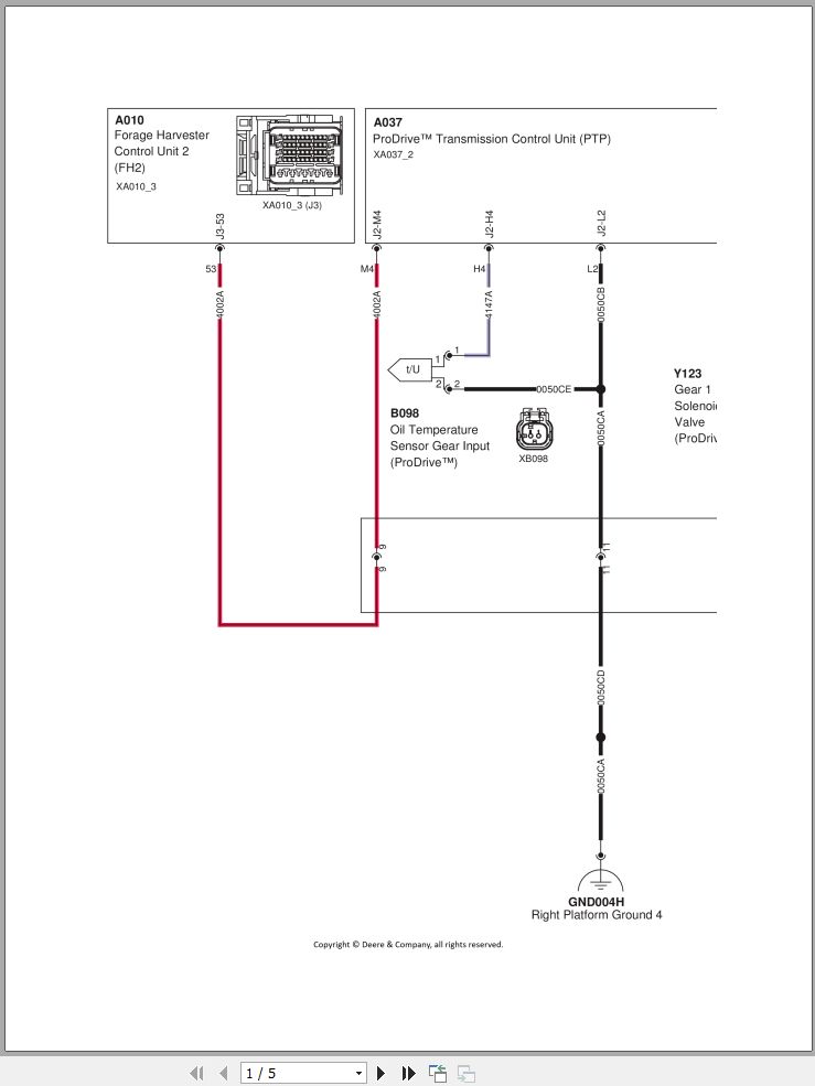
ZX211572-UN_ Transmission – ProDrive™ Transmission – Gear Selection and Park Brake Solenoid Valves, Oil Temperature Sensor, Diagnostic Schematic.pdf
ZX211573-UN_ Transmission – ProDrive™ Transmission – Sensors 1, Diagnostic Schematic.pdf
ZX211574-UN_ Transmission – ProDrive™ Transmission – Sensors 2, Diagnostic Schematic.pdf
ZX211575-UN_ Transmission – ProDrive™ Transmission – Solenoid Valves, Diagnostic Schematic.pdf
ZX211576-UN_ Cutterhead Assembly – Cutterhead Control, Diagnostic Schematic.pdf
ZX211577-UN_ Cutterhead Assembly – Feedroll Control, Diagnostic Schematic.pdf
ZX211578-UN_ Cutterhead Assembly – Stone and Metal Detection, Diagnostic Schematic.pdf
ZX211579-UN_ Cutterhead Assembly – Quickstop Function for Crop Feeding System, Diagnostic Schematic.pdf
ZX211580-UN_ Knife Sharpening Function – Solenoid Valves and Motors, Diagnostic Schematic.pdf
ZX211581-UN_ Knife Sharpening Function – Sensors, Diagnostic Schematic.pdf
ZX211582-UN_ Automatic Header Positioning – Solenoid Valves, Diagnostic Schematic.pdf
ZX211583-UN_ Automatic Header Positioning – Sensors – Diagnostic Schematic.pdf
ZX211584-UN_ Dual Header Drive, Diagnostic Schematic.pdf
ZX211585-UN_ SCV1 _ SCV2 _ Wagon Dump – SCV1 _ SCV2, Diagnostic Schematic.pdf
ZX211586-UN_ SCV1 _ SCV2 _ Wagon Dump – Wagon Dump (Fast Dump Up and Down), Diagnostic Schematic.pdf
ZX211587-UN_ SCV1 _ SCV2 _ Wagon Dump – Wagon Dump, Diagnostic Schematic.pdf
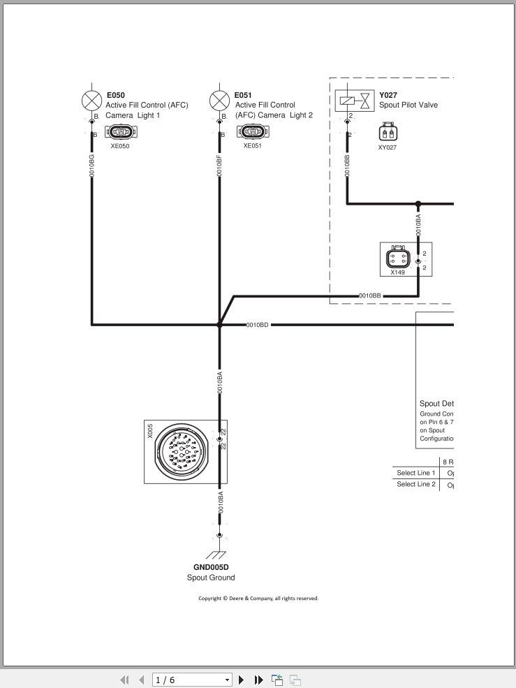
ZX211588-UN_ Spout Control – Actuators, Diagnostic Schematic.pdf
ZX211589-UN_ Spout Control – Spout Detection Matrix, Diagnostic Schematic.pdf
ZX211590-UN_ Spout Control – Sensors, Diagnostic Schematic.pdf
ZX211591-UN_ Miscellaneous Systems – Air Compressor, Diagnostic Schematic.pdf
ZX211592-UN_ Miscellaneous Systems – Central Lubrication System, Diagnostic Schematic.pdf
ZX211593-UN_ Miscellaneous Systems – Washer Pumps, Diagnostic Schematic.pdf
ZX211594-UN_ Kernel Processor, Diagnostic Schematic.pdf
ZX211595-UN_ Miscellaneous Sensor Applications – Diagnostic Schematic.pdf
ZX216005-UN_ HVAC – Actuators for Air Distribution and AC Compressor Clutch, Diagnostic Schematic.pdf
ZX216006-UN_ HVAC – Recirculation and Pressurizer Fan Motor, Diagnostic Schematic.pdf
ZX216007-UN_ HVAC – Sensors, Diagnostic Schematic.pdf
ZX216008-UN_ AMS Systems – AutoTrac™, Diagnostic Schematic.pdf
ZX216009-UN_ AMS Systems – Mass Flow Measurement, Diagnostic Schematic.pdf
ZX216010-UN_ AMS Systems – Telematics Systems and Ethernet Switch, Diagnostic Schematic.pdf
ZX216011-UN_ AMS Systems – RowSense™, Diagnostic Schematic.pdf
ZX216012-UN_ Miscellaneous Systems – Backup Camera and Spout Camera, Diagnostic Schematic.pdf
ZX216013-UN_ Miscellaneous Systems – Additional Cameras, Diagnostic Schematic.pdf
ZX216223-UN_ Lights and Signals – Clearance Lights 1, Diagnostic Schematic.pdf
ZX216224-UN_ Lights and Signals – Clearance Lights 2, Diagnostic Schematic.pdf
ZX216225-UN_ Lights and Signals – Clearance Lights 3, Diagnostic Schematic.pdf
ZX216226-UN_ Lights and Signals – Service Light for Cutterhead Assembly and Central Service Compartment, Diagnostic Schematic.pdf
ZX216227-UN_ Lights and Signals – Service Light for Engine Compartment, Diagnostic Schematic.pdf
ZX216228-UN_ Lights and Signals – Service Light on Ladder and in Tool Box Compartment, Diagnostic Schematic.pdf
ZX216229-UN_ Lights and Signals – Brake Lights, Diagnostic Schematic.pdf
ZX216232-UN_ Lights and Signals – Handrail Work Lights, Diagnostic Schematic.pdf
ZX216233-UN_ Lights and Signals – Work Lights on Gull Wing Doors and Tailgate, Diagnostic Schematic.pdf
ZX216234-UN_ Lights and Signals – Spout Work Lights, Header Work Lights, and Row Finder Lights, Diagnostic Schematic.pdf
ZX216235-UN_ GND001A – Battery Ground 1, Diagnostic Schematic.pdf
ZX216236-UN_ GND001C – Engine Ground 1, Diagnostic Schematic for Machines with Final Tier 4 – Stage IV Engine.pdf
ZX216238-UN_ GND001E – ProDrive™ Transmission Control Unit (PTP) Ground, Diagnostic Schematic.pdf
ZX216239-UN_ GND001F – Rear Ground, Diagnostic Schematic.pdf
ZX216242-UN_ GND002B – Hydraulics Ground 2, Diagnostic Schematic.pdf
ZX216243-UN_ GND002C – Forage Harvester Control Unit 1 (FH1) and Forage Harvester Power Module (CPM1) Ground, Diagnostic Schematic.pdf
ZX216244-UN_ GND003A – Header Ground, Diagnostic Schematic.pdf
ZX216246-UN_ GND003C – Left Cab Platform Ground 2, Diagnostic Schematic.pdf
ZX216247-UN_ GND003D – Left Cab Platform Ground 3, Diagnostic Schematic.pdf
ZX216248-UN_ GND003E – Left Cab Platform Ground 4, Diagnostic Schematic.pdf
ZX216252-UN_ GND004D – Cutterhead Ground 1, Diagnostic Schematic.pdf
ZX219532-UN_ GND004G – Right Cab Platform Ground 3, Diagnostic Schematic.pdf
ZX219533-UN_ GND004H – Right Cab Platform Ground 4, Diagnostic Schematic.pdf
ZX219534-UN_ GND004H – Right Cab Platform Ground 4 (Vehicle, ProDrive™ Transmission Option), Diagnostic Schematic.pdf
ZX219535-UN_ GND004H – Right Cab Platform Ground 4 (Vehicle, 3-Speed Push Button Shift Transmission Option), Diagnostic Schematic.pdf
ZX219537-UN_ GND005B – Central Service Compartment Ground 2, Diagnostic Schematic.pdf
ZX219538-UN_ GND005C – Forage Harvester Control Unit 2 (FH2) and Forage Harvester Power Module (CPM2) Ground, Diagnostic Schematic.pdf
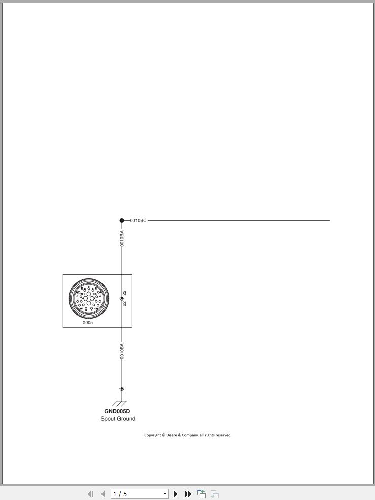
ZX219540-UN_ GND005D – Spout Ground (Flat, US edition), Diagnostic Schematic.pdf
ZX219541-UN_ GND006A – Transmission Ground 1 (3-Speed Push Button Shift Transmission Option), Diagnostic Schematic.pdf
ZX219542-UN_ GND006A – Transmission Ground 1 (ProDrive™ Transmission Option), Diagnostic Schematic.pdf
ZX219543-UN_ GND006B – Transmission Ground 2, Diagnostic Schematic.pdf
ZX219544-UN_ GND006C – Transmission Ground 3 (3-Speed Push Button Shift Transmission Option), Diagnostic Schematic.pdf
ZX219545-UN_ GND006C – Transmission Ground 3 (ProDrive™ Transmission Option), Diagnostic Schematic.pdf
ZX219546-UN_ GND007 – Kernel Processor Winch Ground, Diagnostic Schematic.pdf
ZX219547-UN_ XGND1 – Cab Ground 1, Diagnostic Schematic.pdf
ZX219548-UN_ XGND2 – Cab Ground 2, Diagnostic Schematic.pdf
ZX219549-UN_ XGND3 – Cab Ground 3, Diagnostic Schematic.pdf
ZX219550-UN_ XGND4 – Cab Ground 4, Diagnostic Schematic.pdf
ZX219551-UN_ XGND5 – Cab Ground 5, Diagnostic Schematic.pdf
ZX219552-UN_ XGND7 – Cab Ground 7, Diagnostic Schematic.pdf
ZX219554-UN_ Electronic Cab Systems – Armrest Switch Matrix (ASM) – Diagnostic Schematic.pdf
ZX219555-UN_ Electronic Cab Systems – Audible Alarm, Diagnostic Schematic.pdf
ZX219556-UN_ Electronic Cab Systems – CommandARM™ Controls, Lever on Steering Column, and Horn, Diagnostic Schematic.pdf
ZX219557-UN_ Electronic Cab Systems – Dome Light, Diagnostic Schematic.pdf
ZX219558-UN_ Electronic Cab Systems – Key Switch, Diagnostic Schematic.pdf
ZX219559-UN_ Electronic Cab Systems – Main Clutch Switch, Diagnostic Schematic.pdf
ZX219560-UN_ Electronic Cab Systems – Outside Mirrors, Diagnostic Schematic.pdf
ZX219561-UN_ Electronic Cab Systems – Multi-Function Lever Position Sensor, Diagnostic Schematic.pdf
ZX219562-UN_ Electronic Cab Systems – Multi-Function Lever – Power Supply and Quickstop Function, Diagnostic Schematic.pdf
ZX219563-UN_ Electronic Cab Systems – Multi-Function Lever – Switches (3-Speed Push Button Shift Transmission Option).pdf
ZX219564-UN_ Electronic Cab Systems – Multi-Function Lever – Switches (ProDrive™ Transmission Option).pdf
ZX219565-UN_ Electronic Cab Systems – Radio – Stereo AUX & USB Assembly, Microphone, XM Satellite Radio, and Antenna, Diagnostic Schematic.pdf
ZX219566-UN_ Electronic Cab Systems – Radio – Power Supply and Speakers, Diagnostic Schematic.pdf
ZX219567-UN_ Electronic Cab Systems – Refrigerator and Map Light, Diagnostic Schematic.pdf
ZX219568-UN_ Electronic Cab Systems – Wipers (Front and Rear), Diagnostic Schematic.pdf
ZX219569-UN_ Electronic Cab Systems – Wipers (Left and Right), Diagnostic Schematic.pdf
ZX219570-UN_ 9-L and 13.5-L TIER 4 _ Stage IV Engines – Coolant Level Switch, Diagnostic Schematic.pdf
ZX219571-UN_ 9-L and 13.5-L TIER 4 _ Stage IV Engines – DEF Heaters, Diagnostic Schematic.pdf
ZX219572-UN_ 9-L and 13.5-L Tier 4 _ Stage IV Engines – DEF Tank Header Assembly and DEF Dosing Injector, Diagnostic Schematic.pdf
ZX219573-UN_ 9-L and 13.5-L TIER 4 _ Stage IV Engines – Exhaust Filter Temperature Module, DPF Differential Pressure Sensor, SCR Temperature Module, and DEF Dosing Unit, Diagnostic Schematic.pdf
ZX219574-UN_ 9-L Tier 3 _ Stage IIIA, 9-L and 13.5-L Tier 4 _ Stage IV Engines – Fuel Pump Power Supply, Diagnostic Schematic.pdf
ZX219575-UN_ 9-L and 13.5-L Tier 4 _ Stage IV Engines – NOx Sensors and CAN Bus Terminator for Aftertreatment System, Diagnostic Schematic for machines up to serial number 516000.pdf
ZX219576-UN_ 9-L and 13.5-L TIER 4 _ Stage IV Engines – Ether Starting Aid, Diagnostic Schematic.pdf
ZX219577-UN_ Common Engine Components – Oil Filter Pressure Switch and Power Distribution Gear Oil Temperature Sensor.pdf
ZX219578-UN_ Lights and Signals – Beacon Lights, Diagnostic Schematic.pdf
ZX219579-UN_ Lights and Signals – Cab Roof Lights (HID _ Xenon Option), Diagnostic Schematic.pdf
ZX219580-UN_ Lights and Signals – Cab Roof Lights (HIR _ Halogen Option), Diagnostic Schematic.pdf
ZX219581-UN_ Miscellaneous Systems – Additive Dosing System, Diagnostic Schematic.pdf
ZX219582-UN_ Miscellaneous Systems – Header Multi-Coupler, Diagnostic Schematic.pdf
ZX219584-UN_ Lights and Signals – Cab Platform Lights, Diagnostic Schematic.pdf
ZX219585-UN_ Electronic Cab Systems – Seat Heater, Compressor, and Operator Presence Switch Assembly, Diagnostic Schematic.pdf
ZX238346-UN_ AMS Systems – Active Fill Control, Diagnostic Schematic.pdf
ZX238347-UN_ 19-L TIER 2 _ Stage II Engines – Coolant Level Switch, Low-Pressure Fuel Pump, Water-in-Fuel Sensor and Switch for Engine Air Cleaner.pdf
ZX238348-UN_ 13.5-L Tier 3 _ Stage IIIA, 9-L and 13.5-L Tier 2 _ Stage II Engines – Coolant Level Switch, Low-Pressure Fuel Pump and Switch for Engine Air Cleaner.pdf
ZX260969-UN_ Miscellaneous Systems – ProCut, Diagnostic Schematic.pdf
ZX260976-UN_ 9-L and 13.5-L Tier 4 _ Stage IV Engines – Sensor for DEF Quality, Solenoid Valve for DEF Cooling and DEF Dosing Injector, Diagnostic Schematic.pdf
ZX260977-UN_ 9-L Tier 3 _ Stage IIIA Engines – Control Unit Power Supply, Coolant Level Switch and Switch for Engine Air Cleaner, Diagnostic Schematic.pdf
ZX260978-UN_ 9-L and 13.5-L Tier 4 _ Stage IV Engines – NOx Sensors, Sensor for DEF Quality and CAN Bus Terminator for Aftertreatment System, Diagnostic Schematic for machines from serial number 516.pdf
ZX260982-UN_ Lights and Signals – Left Turn-Signal Lights, Diagnostic Schematic for Machines in the EU.pdf
ZX260983-UN_ Lights and Signals – Left Turn-Signal Lights, Diagnostic Schematic for Machines in the US.pdf
ZX284475-UN_ Lights and Signals – Right Turn-Signal Lights, Diagnostic Schematic for Machines in the EU.pdf
ZX284476-UN_ Lights and Signals – Right Turn-Signal Lights, Diagnostic Schematic for Machines in the US.pdf
ZX284477-UN_ GND001B – Battery Ground 1 (19-L Engine), Diagnostic Schematic.pdf
ZX284478-UN_ GND001C – Engine Ground 1, Diagnostic Schematic for Machines with 13.5-L Tier 3 – Stage III or Tier 2 – Stage II Engine.pdf
ZX284479-UN_ GND001C – Engine Ground 1, Diagnostic Schematic for Machines with 9-L Tier 3 – Stage III Engine.pdf
ZX284480-UN_ GND001D – Fuel Pump Ground, Diagnostic Schematic.pdf
ZX284481-UN_ GND001G, GND001H – Engine Ground 2 (9-L- and 13.5-L Engine), Diagnostic Schematic.pdf
ZX284482-UN_ GND001G, GND001J – Engine Ground 2 (19-L Engine), Diagnostic Schematic.pdf
ZX284483-UN_ GND002A – Hydraulic Ground 1, Diagnostic Schematic.pdf
ZX284485-UN_ GND003B – Left Cab Platform Ground 1, Diagnostic Schematic.pdf
ZX284487-UN_ GND004A – Right Cab Platform Ground 1, Diagnostic Schematic.pdf
ZX284488-UN_ GND004E – Cutterhead Ground 2, Diagnostic Schematic.pdf
ZX284489-UN_ GND004C – AutoTrac™ Control Unit (SBBC) Ground, Diagnostic Schematic.pdf
ZX284490-UN_ GND004F – Right Cab Platform Ground 2, Diagnostic Schematic.pdf
ZX284491-UN_ GND005A – Central Service Compartment Ground 1, Diagnostic Schematic.pdf
ZX284492-UN_ GND005D – Spout Ground, Diagnostic Schematic.pdf
Related Products
-
John Deere Agriculture 13.2 GB PDF Technical Manual Service Manual EN DVD
Original price was: 400.260Current price is: 260. USDJohn Deere Agriculture 13.2 GB PDF Technical Manual Service Manual EN DVDSize: 13.2 GbLanguage: EnglishFormat: PDFBrand: John DeereType of machine: John Deere Agriculture Technical Manual Service ManualWindow: Win 7, Win 8, Win 10 32 & 64 bit, Mac OSAmount of DVD: 1 DVDType of document: Technical Manual Service ManualHigh-Speed Link DownloadJohn Deere Agriculture 13.2 GB PDF Technical Manual Service Manual EN DVDSize: 13.2 GbLanguage: EnglishFormat: PDFBrand: John DeereType of machine: John Deere Agriculture Technical Manual Service ManualWindow: Win 7, Win 8, Win 10 32 & 64 bit, Mac OSAmount of DVD: 1 DVDType of document: Technical Manual Service ManualHigh-Speed Link DownloadHot-35%
REALEASE :
12.07.2021
REALEASE :
12.07.2021
-
John Deere Tractor Full Model List Service Repair Diagnostic Operator Technical Manual
USDLet’s check the model’s list below. (You can use ctrl + F for the search Function)Let me know the models that you want through these email admin@autoepcservice.com or autoepcservice@gmail.comThen I will show you my price.High-Speed Link DownloadREALEASE :
13.05.2022
-
John Deere Lawn and Garden Full Model List Service Repair Diagnostic Operator Technical Manual
USDLet’s check the model’s list below. (You can use ctrl + F for the search Function)Let me know the models that you want through these email admin@autoepcservice.com or autoepcservice@gmail.comThen I will show you my price.High-Speed Link DownloadREALEASE :
13.05.2022
-
John Deere Tractor 15.8 GB PDF Operator’s Manual Updated 2021
Original price was: 300.170Current price is: 170. USDJohn Deere Tractor 15.8 Gb PDF Operation Manual Updated 2021Size: 15.8 GB (PDF Files)Language: EnglishType of manual: Operator’s ManualType of machine: John Deere Tractor AgriculturalFormat: PDFBrand: John DeereOS: All WindowAmount of DVD: 1 DVD_02High-Speed Link DownloadHot-43%
REALEASE :
14.04.2022
REALEASE :
14.04.2022
-
JCB Diagnostic Tool SISU Power WinEEM4 Service Tool 2.7.2
Original price was: 200.100Current price is: 100. USDThis is a diagnostic program. You will need this when you are a technician.Hot-50%
REALEASE :
10.09.2021
REALEASE :
10.09.2021
-
John Deere Agricultural Full Model List Service Repair Diagnostic Operator Technical Manual
USDLet’s check the model’s list below. (You can use ctrl + F for the search Function)Let me know the models that you want through these email admin@autoepcservice.com or autoepcservice@gmail.comThen I will show you my price.High-Speed Link DownloadREALEASE :
13.05.2022
-
John Deere Service Manual PDF Collection 1.55 GB
Original price was: 300.180Current price is: 180. USDThis is a service information package, you will need to use this to repair a vehicleHot-40%
REALEASE :
REALEASE :
-
John Deere Agricultural 25.1GB PDF Technical Manual Service Manual DVD
Original price was: 800.440Current price is: 440. USDJohn Deere Agricultural 25.1GB PDF Technical Manual Service Manual DVDSize: 25.1 Gb (PDF Files)Type of manual: Technical Manual Service ManualType of machine: John Deere AgricultureLanguage: English, German, Spanish, French, Lettisch, Tschechisch, Schwedish, Portuguese, Czech, Hungarian, Swedish, Dutch, Danish, BulgarischFormat: PDFBrand: John Deere, Hagie, Macdone, Rework, Roberine, DanfossOS: All WindowAmount of DVD: 1 DVDType of document: Technical Manual Service ManualHigh-Speed Link DownloadHot-45%
REALEASE :
12.21.2021
REALEASE :
12.21.2021


