
0 ITEMSVIEW CART

✓
Expert Support
✓
Full Speed
✓
100% Working
John Deere Round Baler 447 457 467 Silage Special 547 557 567 Repair Manual TM1874
Size: 20.96 MB
Format: PDF
Language: English
Brand: John Deere
Type of Machine: Round Baler
Type of Manual: Repair Manual
Model: John Deere 447, 457, 467 Silage Special, 547, 557, 567 Round Baler
Serial Number: -300000
Part Number: TM1874
Publication Date: 2020
Number of Pages: 695 Pages
50 USD
- Description
Description
Contents:
General
Safety
Recognize Safety Information
Understand Signal Words
Follow Safety Instructions
Operate Baler Safely
Protect Bystanders
Handle Fluids Safely—Avoid Fires
Prepare for Emergencies
Fire Prevention
Fire Prevention—Welding
Avoid High-Pressure Fluids
Support Machine Properly
Wear Protective Clothing
Work in Clean Area
Service Machine Safely
Illuminate Work Area Safely
Replace Safety Signs
Use Proper Lifting Equipment
Remove Paint Before Welding or Heating
Avoid Heating Near Pressurized Fluid Lines
Service Tires Safely
Practice Safe Maintenance
Use Proper Tools
Construct Dealer-Made Tools Safely
Decommissioning — Proper Recycling and Disposal of Fluids and Components
Live With Safety
Specifications
Machine Specifications—447 and 547
Machine Specifications—457, 457 Silage Special and 557
Machine Specifications—467, 467 Silage Special, and 567
Metric Bolt and Screw Torque Values
Unified Inch Bolt and Screw Torque Values
Face Seal Fittings Assembly and Installation—All Pressure Applications
Metric Face Seal Fitting Torque Chart—Standard Pressure Applications
Metric Face Seal Fitting Torque Chart—High Pressure Applications
SAE Face Seal Fitting Torque Chart—Standard Pressure Applications
SAE Face Seal Fitting Torque Chart—High Pressure Applications
Service Recommendations For 37° Flare and 30° Cone Seat Connectors
General Information
Machine Description—447 and 547
Machine Description—457, 457 Silage Special, and 557
Machine Description—467, 467 Silage Special, and 567
Lubricants
Multipurpose Extreme Pressure (EP) Grease
Gear Case Oil
Alternative and Synthetic Lubricants
Mixing of Lubricants
Lubricant Storage
Perform Lubrication and MaintenanceDrive Train
General Information
Drive Train Operation
Operating RPM
Diagnosing Malfunctions
PTO Driveline Difficulties
Shear Bolt Difficulties (447, 457, 457S, 547, and 557)
Slip Clutch Difficulties (If Equipped)
Gear Case Difficulties
Drive Chain Difficulties
Drive Train Protection
Service Parts Kits
Specifications
Replace Driveline Shear Bolt (447, 457, 457S, 547, and 557)
Repair PTO Driveline Hub—Shear Bolt Type (447, 457, 457S, 547, and 557)
Repair PTO Driveline Hub—Slip Clutch Type
Repair PTO Driveline Slip Clutch (If Equipped)
Adjust PTO Driveline Slip Clutch (If Equipped)
Slipping Seized PTO Driveline Slip Clutch (If Equipped)
PTO Driveline
Other Material
Service Parts Kits
Specifications
PTO Driveline Exploded View—Shear Bolt Type (447, 457, 457S, 547, and 557)
PTO Driveline Exploded View—Slip Clutch Type
Repair PTO Lock-Back Collar Disconnect
Repair PTO Constant Velocity Joint
Replace Centralizer Bearing
Gear Case Repair
Essential or Recommended Tools
Service Equipment and Tools
Other Material
Specifications
Remove Gear Case
Disassemble Gear Case
Inspect Gear Case
Assemble Gear Case
Install Gear Case
Convert Baler to 1000 RPM (467, 467S, and 567)
Roll Drives
Specifications
Adjust Lower Drive Roll Chain
Adjust Upper Drive Roll Chain—447, 457, 457S, 547, and 557
Adjust Upper Drive Roll Chain—467, 467S, and 567
Check Starter Roll Drive Chain
Adjust Starter Roll Drive Chain
Replace Starter Roll Drive Chain
Check Upper Drive Roll Sprocket Alignment—447, 457, 457S, 547, and 557
Check Upper Drive Roll Sprocket Alignment—467, 467S, and 567
Rotate or Replace Upper Drive Roll Chain Idler Bushing (467, 467S, and 567)
Rotate or Replace Upper Drive Roll Chain Guides (467, 467S, and 567)
Rolls
Essential or Recommended Tools
Service Equipment and Tools
Other Material
Specifications
Diagram of Rolls and Belt Routing—447-547
Diagram of Rolls and Belt Routing—457, 557, 467, and 567
Diagram of Rolls and Belt Routing—457S and 467S
Remove and Install Starter Roll
Remove Lower Drive Roll
Install Lower Drive Roll
Remove and Install Belt Staggering Roll
Remove and Install Cleaning Auger Roll (457S and 467S)
Remove and Install Front Idler Roll—457, 457S, and 557
Remove and Install Front Idler Roll—467, 467S, and 567
Remove Upper Drive Roll
Install Upper Roll
Remove and Install Take-Up Arm Roll
Remove and Install Top Idler Roll—All Models Except 457S
Remove and Install Top Idler Roll—457S
Remove and Install Upper Rear Gate Roll
Remove and Install Lower Rear Gate Roll—Without COVEREDGE Net Wrap
Remove and Install Lower Rear Gate Roll—With COVEREDGE Net Wrap (457, 457S, 467, 467S, 557 and 567)
Remove and Install Lower Front Gate Roll
Remove and Install Rear Roll of Tension Arm (447, 457, 457S, 547, and 557)
Remove and Install Center and Front Rolls of Tension Arm (447, 457, 457S, 547, and 557)
Remove and Install Center and Rear Tension Arm Rolls (467, 467S, and 567)
Remove and Install Front Tension Arm Roll (467, 467S, and 567)
Replace Tension Arm Roll Shaft
Prepare Live Shaft Rolls for Installation
Replace Stationary Shaft Roll Bearings
Miscellaneous
Service Equipment and Tools
Specifications
Adjust Lower Front Gate Roll Scraper
Adjust Starter Roll Scraper (If Equipped)
Check Belt Tracking
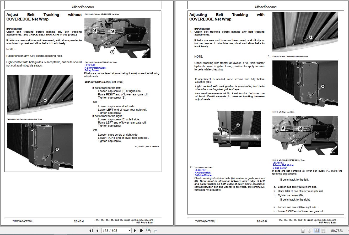
Adjust Belt Tracking without COVEREDGE Net Wrap
Adjusting Belt Tracking with COVEREDGE Net WrapHydraulics
General Information
Hydraulic System Description and Diagram—447 and 547
Hydraulic System Description and Diagram—457, 457S, and 557
Hydraulic System Description and Diagram—467, 467S, and 567
Tensioning Valve—447, 457, 457S, 547, and 557
Tensioning Valve—467, 467S, and 567
Non-Adjustable Relief Valve
Adjustable Relief Valve (467, 467S, and 567)
Pilot-Operated Check Valve—447, 457, 457S, 547, and 557
Pilot-Operated Check Valves—467, 467S and 567
Optional Variable (Soft) Core Solenoid Valve (457, 457S, 467, 467S, 557, and 567)
Install Inline Orifice Correctly (457, 457S, 467, 467S, 557, and 567)
Bale Density Gauge (467, 467S, and 567)
Diagnosing Malfunctions
Diagnosing Hydraulic Malfunctions—447, 457, 457S, 547, and 557
Diagnosing Hydraulic Malfunctions—467, 467S, and 567
Operation and Tests-447, 457, 457S, 547 and 557
Essential or Recommended Tools
Specifications
Hydraulic System Operation—447 and 547
Hydraulic System Operation—457, 457S, and 557
Low Pressure Relief Valve Test
High Pressure Relief Valve Test
Test Tension/Gate Cylinder For Leakage
Test Hydraulic Twine Arm and Pickup Lift Cylinders for Leakage
Test Take-Up Arm Cylinder (457, 457S and 557)
Test Gate Lock Valve for Leakage (457, 457S, and 557)
Operation and Tests-467, 467S and 567
Essential or Recommended Tools
Specifications
Hydraulic System Operation
Low Pressure Relief Valve Test
Check Adjustable Relief Valve
Test Tension or Gate Cylinder for Leakage
Test Pickup Lift Cylinder for Leakage
Test Gate Lock Valve for Leakage
Tensioning Valve Repair-447, 457, 457S, 547 and 557
Remove and Install Tensioning Valve
Disassemble and Inspect Tensioning Valve
Assemble Tensioning Valve
Check Condition of Valve Seat and Poppet
Tensioning Valve Repair-467, 467S and 567
Remove and Install Tensioning Valve
Disassemble and Inspect Tensioning Valve
Assemble Tensioning Valve
Check Condition of Valve Seat and Poppet
Install Check Valves Correctly
Gate Lock Valve Repair (457, 457S, 467, 467S, 557 and 567)
Specifications
Repair Gate Lock Valve
Adjust Gate Lock Valve Interlock Lever (457, 457S, and 557)
Cylinder Repair
Identify Hydraulic Cylinder
Essential or Recommended Tools
Service Parts Kits
Specifications
Remove and Install Tension/Gate Cylinder—447 and 547
Remove and Install Tension/Gate Cylinder—457, 457S and 557
Remove and Install Gate Cylinder—467, 467S and 567
Remove and Install Tension Cylinder—467, 467S and 567
Disassemble and Inspect Tension/Gate Cylinder
Assemble Tension/Gate Cylinder
Repair Twine Arm or Pickup Lift Cylinder (If Equipped)
Optional Hydraulic Bale Ramp Repair (457, 457S and 557)
Repair Hydraulic System for Hydraulic Bale RampTwine Mechanism-Hydraulic (447, 457, 457S, 547, and 557)
General Information
Twine Wrap System Description
Operating Twine Wrap Control
Adjust Twine Spacing (Double Twine Wrap)
Diagnosing Malfunctions
Diagnosing Twine Wrap Malfunctions
Twine Wrap System Adjustments
Specifications
Adjust Twine Arm-to-Starter Roll, Cutter Link Support, and Twine Arm Stop
Adjust Twine Arm Distance From Right Sidesheet—447, 457, and 457S
Adjust Twine Arm Distance From Right Sidesheet—547 and 557
Adjust Twine Cutter-to-Twine Arm Clearance
Adjust Twine Cutter Knife
Adjust Twine Cutter Contact Tab
Adjust Clearance Between Cutter Link Support and Twine Arm
Adjust Twine Cutter Tension
Adjust Front Twine Arm (Double Twine Arms)
Adjust Twine Indicator Retaining Strap
Adjust Twine End Spacing with Mechanical Twine Guides
Twine Wrap System Repair
Other Material
Specifications
Remove Hydraulic Twine Arm Cylinder—447, 457, and 457S
Install Hydraulic Twine Arm Cylinder—447, 457, and 457S
Attach Hydraulic Cylinder End Block to Twine Arm—447, 457, and 457S
Remove Hydraulic Twine Arm Cylinder—547 and 557
Install Hydraulic Twine Arm Cylinder—547 and 557
Adjust Initial Length of Hydraulic Twine Arm Cylinder
Install Twine Arm Stop—447, 457, and 457S
Install Twine Arm Stop—547 and 557
Install Twine Arm and Twine Arm Drive Gear (547 and 557)Twine Mechanism-Electric
General Information
Twine Wrap System Description—447 and 547
Twine Wrap System Description—457, 457S, 467, 467S, 557 and 567
Operate Twine Wrap Controller (447 and 547)
Understanding Twine Wrap Terms and Settings (457, 457S, 467, 467S, 557 and 567)
Diagnosing Malfunctions
Twine Wrap Difficulties—447 and 547
Twine Wrap Difficulties—457, 457S, 467, 467S, 557 and 567
BALETRAK PLUS Monitor-Controller Difficulties (457, 457S, 467, 467S, 557 and 567)
Twine Wrap System Adjustments-447 and 547
Specifications
Adjust Twine Arm-to-Starter Roll, Cutter Link Support, and Twine Arm Stop
Adjust Twine Arm Distance From Right Sidesheet (447)
Adjust Twine Cutter-to-Twine Arm
Adjust Twine Cutter Knife
Adjust Twine Cutter Contact Tab
Adjust Clearance Between Cutter Link Support and Twine Arm
Adjust Twine Cutter Tension
Adjust Front Twine Arm (If Equipped)
Adjust Twine Indicator Retaining Strap
Adjust Twine Guide(s) (If Equipped)
Adjust Twine Spacing (Double-Twine Wrap)
Twine Wrap System Adjustments-457, 457S, 467, 467S, 557 and 567
Specifications
Adjust Twine Arm-to-Starter Roll, Cutter Link Support, and Twine Arm Stop
Adjust Twine Cutter-to-Twine Arm
Check and Adjust Twine Cutter Knife
Adjust Twine Cutter Contact Tab
Adjust Clearance Between Cutter Link Support and Twine Arm
Adjust Twine Cutter Tension
Adjust Front Twine Arm
Adjust Twine Indicator Retaining Strap
Set Twine End Wrap Distance
Set Twine Spacing
Twine Wrap System Repair
Specifications
Remove and Install Twine Arm Actuator—447, 457, 457S, 467, and 467S
Install Twine Arm Actuator, Adapter, and Pivot Assembly—447, 457, 457S, 467, and 467S
Remove and Install Twine Arm Actuator—547, 557, and 567
Install Twine Arm Actuator, Adapter, and Pivot Assembly—547, 557, and 567
Install Twine Arm Stop—447, 457, 457S, 467, and 467S
Install Twine Arm Stop—547, 557, and 567
Install Twine Arm and Twine Arm Drive Gear (547, 557, and 567)COVEREDGE Net Wrap System (If Equipped)
General Information
Other Material
Specifications
System Description
Switch Description
Wrap Bale
Adjust Delay
Correct Feeding Problems
Prepare Net Wrap After Extended Storage
Diagnosing Malfunctions
Diagnosing Malfunctions
BALETRAK PLUS Monitor-Controller Difficulties
Net Wrap Repair
Essential or Recommended Tools
Specifications
Remove and Install Net Wrap Assembly
Repair Cuts on Feed Roll
Remove and Install Upper (Rubber) Feed Roll
Replace Upper Feed Roll Bearings
Remove and Install Lower (Steel) Feed Roll
Install Lower Net Wrap Guide
Adjust Lower Net Wrap Guide
Replace Lower Front Gate Roll Belt Guide
Replace Cover Hinge Seal
Check Cover Gas Springs
Check and Adjust Cover Latch
Remove Net Wrap Actuator
Install Net Wrap Actuator
Remove and Install Net Wrap V-Belt
Check and Adjust Net Wrap V-Belt Idler Tension
Check and Adjust Net Wrap Switch
Test Net Wrap Switch—Monitor-Controller Assisted Test (Channel 10)
Replace Net Wrap Switch or Switch Arm
Remove and Install Cutoff Knife
Sharpen Cutoff Knife
Check and Adjust Net Wrap Feed Roll Brake
Adjust Feed Roll Pressure
Adjusting Net Wrap StretchElectrical System
General Information
Electrical System Description (447 and 547)
Electrical System Description—BALE WATCH Monitor (457, 457S, and 557)
Electrical System Description—BALETRAK PLUS (457, 457S, 467, 467S, 557, and 567)
Tail Lights and Warning Lights
Lighting Enhancement Module Operation
Common Electrical Tests and Checks
Service Equipment and Tools
Electromagnetic Interference (EMI)
Basic Informational Warnings for Machines Equipped With Computer Controlled Systems
Checks Before Testing
Electrical Circuit Definition
Electronic Circuit Definition
Common Circuit Test
Electrical Circuit Malfunctions
Probe Light Check—Voltage from Battery
Probe Light Check—Continuity to Ground
Seven-Step Electrical Test Procedure
Diagnosing Malfunctions-447, 547, and BALE WATCH System
Diagnosing Malfunctions
Diagnosing Malfunctions-BALETRAK PLUS System
Diagnosing Malfunctions
BALETRAK PLUS Monitor-Controller—Activating Alarms
Tests and Adjustments-447, 547, and BALE WATCH System
Specifications
Test Bale Size (Buzzer) Circuit
Adjust Bale Size Switch
Adjust Bale Size Link For Maximum Bale Size (Oversize Warning)
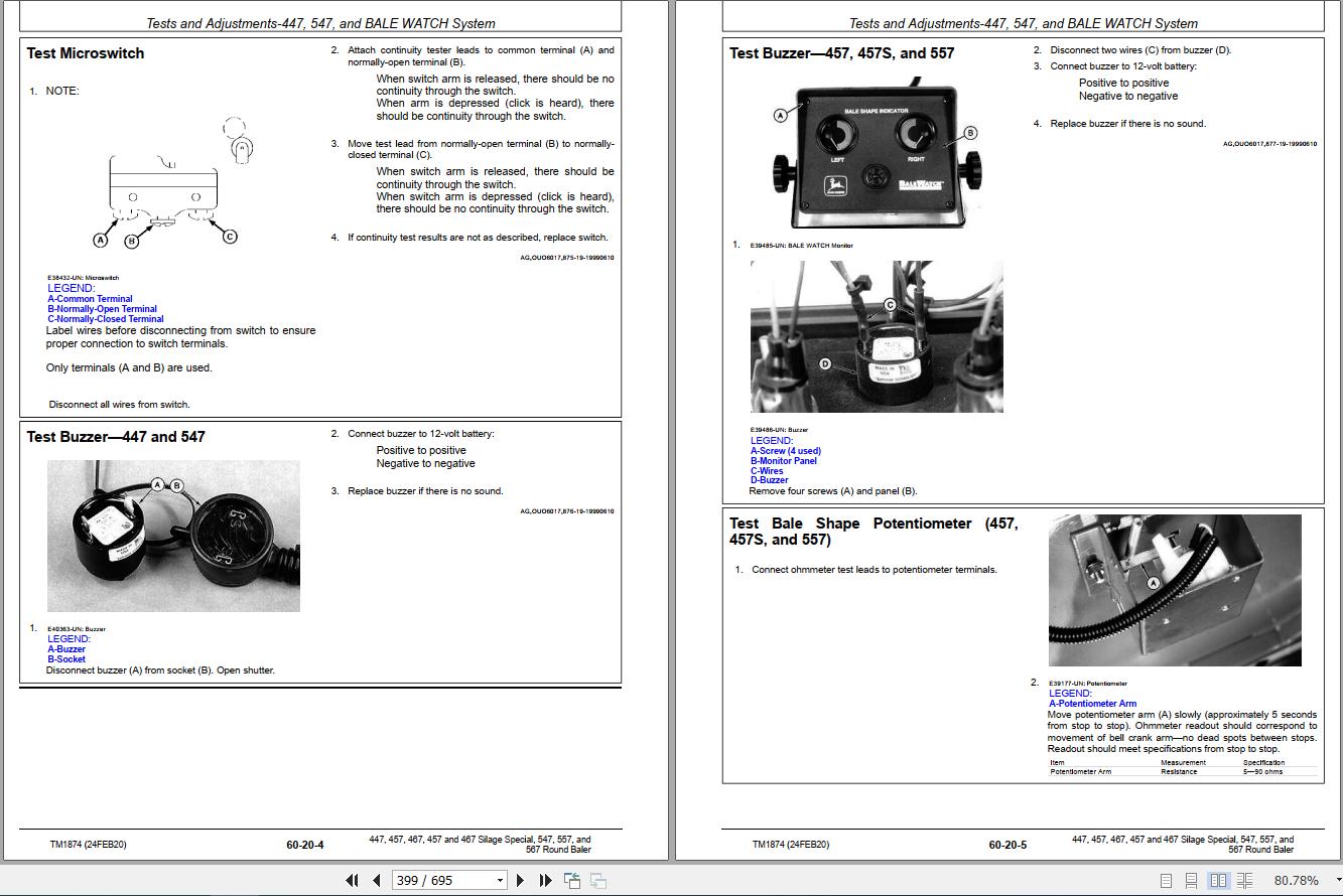
Test Microswitch
Test Buzzer—447 and 547
Test Buzzer—457, 457S, and 557
Test Bale Shape Potentiometer (457, 457S, and 557)
Adjust Bale Shape Potentiometer (457, 457S, and 557)
Test Bale Shape Indicator (457, 457S, and 557)
Test Wires for Continuity—BALE WATCH Circuit (457, 457S, and 557)
Adjust Optional Variable (Soft) Core Switch (457, 457S, and 557)
Tests and Adjustments-BALETRAK PLUS System
Essential or Recommended Tools
Service Equipment and Tools
Specifications
BALETRAK PLUS Monitor-Controller—Diagnostic and Setup Modes
BALETRAK PLUS Monitor-Controller—Diagnostic and Setup Channels
Test Optional Net Wrap Switch (Channel 10)
Test Gate Latch and Oversize Bale Switches (Channels 11, 12 and 13)
Test Twine or Net Wrap Actuator Current (Channel 14)
Test Convenience Outlet Voltage (Channel 15)
Test Monitor-Controller Liquid Crystal Display (LCD) (Channel 16)
Test Baler Switches (Bench Test Method)
Test Sensors
Adjust Twine Wrap Sensor (Channel 03)
Adjust Bale Diameter Sensor (Channel 05) 457, 457S and 557
Adjust Bale Diameter Sensor (Channel 05) 467, 467S and 567
Adjust Bale Diameter Display—All Balers
Adjust Bale Shape Sensor (Channels 07 and 09)
Adjust Bale Shape Bar Display—Field Procedure (Channels 07 and 09)
Adjust Bale Shape Bar Display (Channels 07 and 09)
Adjust Bale Shape Sensitivity (Channel 24)
Adjust Gate Latch Switch(es)
Adjust Oversize Bale Switch 467, 467S and 567
Adjusting Oversize Bale Switch 457, 457S and 557
Electrical Diagrams-447, 547, and BALE WATCH System
Wire Color Chart
Baler Wiring Harness Diagram—447 and 547
Baler Wiring Harness Diagram BALE WATCH System
BALE WATCH System Wiring Diagram
Wiring Diagram—Electric Twine Wrap (447 and 547)
Wiring Diagram—Variable (Soft) Core Option (with BALE WATCH)
Electrical Diagrams-BALETRAK PLUS System
BALETRAK PLUS System Component Locations
Wiring Harness Diagram—BALETRAK PLUS Monitor-Controller
Wiring Harness Diagram—Baler
Wiring Diagram—BALETRAK PLUS Control System
BALETRAK PLUS Monitor-Controller Operations
BALETRAK PLUS Monitor-Controller—Keys and Switches
BALETRAK PLUS Monitor-Controller—Display and Indicators
BALETRAK PLUS Monitor-Controller—Operation
BALETRAK PLUS Monitor-Controller—Specifications
BALETRAK PLUS Monitor-Controller—Setup Values and Initial Settings
BALETRAK PLUS Monitor-Controller—Change Baler Model Program
BALETRAK PLUS Monitor-Controller—Change Display to Metric or English Units
BALETRAK PLUS Monitor-Controller—Display or Reset Bale Counter Memory
BALETRAK PLUS Monitor-Controller—Reset to Initial Settings (Channel 01)
BALETRAK PLUS Monitor-Controller—Adjust Audible Alarm Volume
BALETRAK PLUS Monitor-Controller—Using Extend, Retract, and Wrap Keys
BALETRAK PLUS Monitor-Controller—Using By-Pass Switch (Twine Wrap Only)
Repair-447, 547, and BALE WATCH System
Other Material
Replace Bale Size Switch
Replace Bale Shape Potentiometer (457, 457S, and 557)
Replace Bale Shape Indicators (457, 457S, and 557)
Repair-BALETRAK PLUS System
Service Equipment and Tools
Specifications
Programming BaleTrak™ Pro
Replace BALETRAK PLUS Monitor-Controller Fuse and Relays
Replace BALETRAK PLUS Monitor-Controller LCD Backlight Bulbs
Replace BALETRAK PLUS Monitor-Controller Rocker Switch
Replace BaleTrak™ Pro Computer Chip (EEPROM)
Replace Twine Wrap Sensor
Replace Bale Diameter Sensor
Replace Bale Shape Sensor
Replace Gate Latch Switch(es)
Replace Oversize Bale Switch
Replace Variable (Soft) Core Solenoid Coil (If Equipped)
Connector Repair
Essential or Recommended Tools
Other Material
Electrical Connector Handling
Use Terminal Cleaner and Di-Electric Grease
Connector Identification
Replace WEATHER PACK Connector
Install WEATHER PACK Terminal
Remove Connector Body from Blade Terminals
Replace DEUTSCH Connectors
Install DEUTSCH Terminal Connectors
Replace CPC Blade Type Connectors
Replace Small MATE-N-LOC Pin Connector
Harness Repair—Splice Connector
Harness Repair (Splice, Broken or Cut Wire)Pickup
General Information
Pickup Description
Preliminary Checks
Check Pickup Tooth End Play
Diagnosing Malfunctions
Pickup Difficulties
Feeding Difficulties
Regular Pickup Repair
Service Equipment and Tools
Other Material
Specifications
Replace Teeth (Pickup Installed)
Replace Cam Follower Bearings
Remove and Install Pickup
Disassemble Pickup
Inspect Pickup Components
Assemble Pickup
Pickup Drive Belt and Chain Alignment
Adjust Initial Length of Drive Belt Idler Spring
Adjust Drive Belt Idler
Adjust Pickup Float Springs
MEGATOOTH Pickup Repair
Service Equipment and Tools
Other Material
Specifications
Replace Teeth (Pickup Installed)
Replace Cam Follower Bearings—Left-Hand Side
Replace Cam Follower Bearings—Right-Hand Side
Remove and Install Pickup
Disassemble Pickup
Inspect Pickup Components
Assemble Pickup
Pickup Drive Chains Alignment
Adjust Drive Chain
Adjust Float Springs
MegaWide Pickup Repair
Service Equipment and Tools
Other Material
Specifications
Replace Teeth (Pickup Installed)
Replace Cam Follower Bearings
Remove and Install Pickup
Disassemble Pickup
Inspect Pickup Components
Assemble Pickup
Remove and Install Auger/Rotor Assembly
Disassemble and Assemble Auger/Rotor Assembly
Pickup Drive Chains Alignment
Adjust Auger Scrapers
Adjust Pickup Drive Chains
Adjust Pickup Float Springs
Miscellaneous
Service Equipment and Tools
Specifications
Adjust Initial Length of Hydraulic Lift Cylinder (If Equipped)
Check Slip Clutch Torque (MEGATOOTH or MegaWide)
Repair Slip Clutch
Repair Gauge Wheel—Regular and MEGATOOTH Pickups
Repair Gauge Wheel—MegaWide PickupMiscellaneous
Wheel Repair
Service Equipment and Tools
Specifications
Remove and Install Baler Wheel
Inspect and Replace Baler Wheel Bearings
Repair Gathering Wheel (If Equipped)
Remove Excessive Play from Gathering Wheel Pivot
Gate Repair-447, 457, 457S, 547, and 557
Specifications
Straighten Gate
Remove and Install Gate
Attach Bale Shape Indicator Cables (447 and 547)
Adjust Gate Lock Rod (447 and 547)
Gate Repair-467, 467S, and 567
Specifications
Straighten Gate
Remove and Install Gate
Adjust Gate Latch Stop
Adjust Gate Latch Linkage
Tension Arm Repair-447, 457, 457S, 547, and 557
Specifications
Remove and Install Tension Arm—447 and 547
Remove and Install Tension Arm—457, 457S, and 557
Adjust Take-Up Arm Spring—447 and 547
Adjust Take-Up Arm Spring—457, 457S, and 557
Adjust Bale Size Indicator
Replace Tension Arm Wear Channel
Tension Arm Repair-467, 467S, and 567
Specifications
Remove and Install Tension Arm
Adjust Take-Up Arm Spring
Adjust Bale Size Indicator
Replace Tension Arm Wear Channel
Tongue Repair
Specifications
Remove and Install Tongue
Belt Repair
Essential or Recommended Tools
Service Equipment and Tools
Specifications
Remove Belts—447 and 547
Install Belts—447 and 547
Remove Belts—457, 457S, 467, 467S, 557, and 567
Install Belts—457, 457S, 467, 467S, 557, and 567
Prepare Belts For New Lacings
Install Belt Lacing—447 and 547
Install Belt Lacing—457, 457S, 467, 467S, 557, and 567
Belts Eligible for Warranty Replacement
Belts Not Eligible for Warranty Replacement
Main Frame Repair
Service Equipment and Tools
Straighten Main FrameDealer Fabricated Tools
Dealer Fabricated Tools
DFEX1874A Support StrapPage Number
Related Products
-
John Deere Lawn and Garden Full Model List Service Repair Diagnostic Operator Technical Manual
USDLet’s check the model’s list below. (You can use ctrl + F for the search Function)Let me know the models that you want through these email admin@autoepcservice.com or autoepcservice@gmail.comThen I will show you my price.High-Speed Link DownloadREALEASE :
13.05.2022
-
John Deere Tractor 15.8 GB PDF Operator’s Manual Updated 2021
Original price was: 300.170Current price is: 170. USDJohn Deere Tractor 15.8 Gb PDF Operation Manual Updated 2021Size: 15.8 GB (PDF Files)Language: EnglishType of manual: Operator’s ManualType of machine: John Deere Tractor AgriculturalFormat: PDFBrand: John DeereOS: All WindowAmount of DVD: 1 DVD_02High-Speed Link DownloadHot-43%
REALEASE :
14.04.2022
REALEASE :
14.04.2022
-
John Deere Agricultural Full Model List Service Repair Diagnostic Operator Technical Manual
USDLet’s check the model’s list below. (You can use ctrl + F for the search Function)Let me know the models that you want through these email admin@autoepcservice.com or autoepcservice@gmail.comThen I will show you my price.High-Speed Link DownloadREALEASE :
13.05.2022
-
John Deere Agriculture 13.2 GB PDF Technical Manual Service Manual EN DVD
Original price was: 400.260Current price is: 260. USDJohn Deere Agriculture 13.2 GB PDF Technical Manual Service Manual EN DVDSize: 13.2 GbLanguage: EnglishFormat: PDFBrand: John DeereType of machine: John Deere Agriculture Technical Manual Service ManualWindow: Win 7, Win 8, Win 10 32 & 64 bit, Mac OSAmount of DVD: 1 DVDType of document: Technical Manual Service ManualHigh-Speed Link DownloadJohn Deere Agriculture 13.2 GB PDF Technical Manual Service Manual EN DVDSize: 13.2 GbLanguage: EnglishFormat: PDFBrand: John DeereType of machine: John Deere Agriculture Technical Manual Service ManualWindow: Win 7, Win 8, Win 10 32 & 64 bit, Mac OSAmount of DVD: 1 DVDType of document: Technical Manual Service ManualHigh-Speed Link DownloadHot-35%
REALEASE :
12.07.2021
REALEASE :
12.07.2021
-
John Deere Tractor Full Model List Service Repair Diagnostic Operator Technical Manual
USDLet’s check the model’s list below. (You can use ctrl + F for the search Function)Let me know the models that you want through these email admin@autoepcservice.com or autoepcservice@gmail.comThen I will show you my price.High-Speed Link DownloadREALEASE :
13.05.2022
-
JCB Diagnostic Tool SISU Power WinEEM4 Service Tool 2.7.2
Original price was: 200.100Current price is: 100. USDThis is a diagnostic program. You will need this when you are a technician.Hot-50%
REALEASE :
10.09.2021
REALEASE :
10.09.2021
-
John Deere Agricultural 25.1GB PDF Technical Manual Service Manual DVD
Original price was: 800.440Current price is: 440. USDJohn Deere Agricultural 25.1GB PDF Technical Manual Service Manual DVDSize: 25.1 Gb (PDF Files)Type of manual: Technical Manual Service ManualType of machine: John Deere AgricultureLanguage: English, German, Spanish, French, Lettisch, Tschechisch, Schwedish, Portuguese, Czech, Hungarian, Swedish, Dutch, Danish, BulgarischFormat: PDFBrand: John Deere, Hagie, Macdone, Rework, Roberine, DanfossOS: All WindowAmount of DVD: 1 DVDType of document: Technical Manual Service ManualHigh-Speed Link DownloadHot-45%
REALEASE :
12.21.2021
REALEASE :
12.21.2021
-
John Deere Service Manual PDF Collection 1.55 GB
Original price was: 300.180Current price is: 180. USDThis is a service information package, you will need to use this to repair a vehicleHot-40%
REALEASE :
REALEASE :


