
1 ITEMVIEW CART

Total: 110.00


Expert Support
Full Speed
100% Working
300 USD
Contents:
Introduction
Foreword
General
Safety
Combine and Component Identification
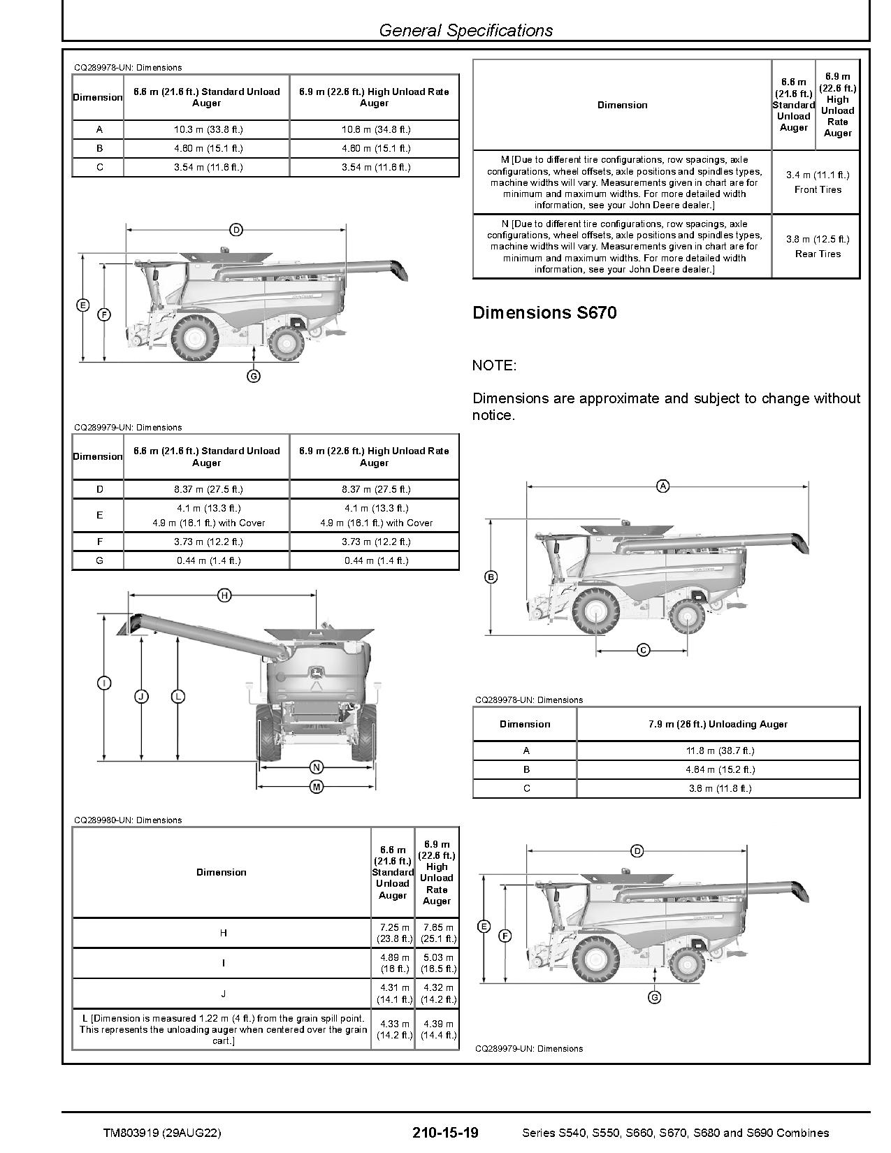
General Specifications
Diagnostic and Testing Procedures
Diagnostic Trouble Codes
Accessing Diagnostic Codes and Addresses
ATC – Diagnostic Trouble Codes
AYM – Diagnostic Trouble Codes
CAB – Diagnostic Trouble Codes
CRU – Diagnostic Trouble Codes
CSM – Diagnostic Trouble Codes
ECU – Tier 2 and Tier 3 Engines – Diagnostic Trouble Codes
EIC – Diagnostic Trouble Codes
GLM – Diagnostic Trouble Codes
JDL – Diagnostic Trouble Codes
LC1 – Diagnostic Trouble Codes
LC2 – Diagnostic Trouble Codes
MHC – Diagnostic Trouble Codes
PDU – Diagnostic Trouble Codes
PTP – Diagnostic Trouble Codes
RC1 – Diagnostic Trouble Codes
RC2 – Diagnostic Trouble Codes
SCL – Diagnostic Trouble Codes
SFC – Diagnostic Trouble Codes
SSU – Diagnostic Trouble Codes
VTi – Diagnostic Trouble Codes
XMC – Diagnostic Trouble Codes
XSC – Diagnostic Trouble Codes
Observable Symptoms
Air Intake and Cooling Systems
Electrical System
Electrical Control Units
Drives – S540 S550 S660 S670
Drives – S680
Steering and Brakes – S540 S550 S660 S670
Steering and Brakes – S680
Hydraulic System – S540 S550 S660 S670
Hydraulic System – S680
Main Gearcase – S540 S550 S660 S670
Main Gearcase – S680
Cab/Open Operator Station
Engine System
Engine Systems
Air Intake and Cooling System
Theory of Operation
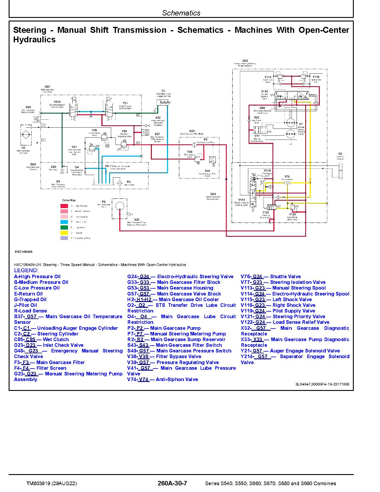
Schematics
Diagnostics
Air Intake and Cooling System – Components
Air Intake and Cooling System – A Components
Air Intake and Cooling System – B Components
Air Intake and Cooling System – D Components
Air Intake and Cooling System – F Components
Air Intake and Cooling System – H Components
Air Intake and Cooling System – P Components
Air Intake and Cooling System – R Components
Air Intake and Cooling System – S Components
Air Intake and Cooling System – V Components
Air Intake and Cooling System – X Components
Electrical System
General Information
General References
Calibration Procedures
Theory of Operation – Cab/Operator`s Station
Theory of Operation – Ag Management Solutions
Theory of Operation – Lighting
Theory of Operation – Engine/Fuel
Theory of Operation – Starting/Charging/Power Distribution
Theory of Operation – Header Functions
Theory of Operation – Feeder House
Theory of Operation – Threshing/Separating/Cleaning
Theory of Operation – Grain Tank/Unloading
Theory of Operation – Residue System
Theory of Operation – Transmission/Ground Drive Systems
Theory of Operation – Hydraulic Oil/Pressure
Theory of Operation – Main Gearcase
Theory of Operation – Brakes
Theory of Operation – Chassis
Theory of Operation – Air Compressor System
Schematics – Cab/Operators Station
Schematics – Ag Management Solutions
Schematics – Lighting
Schematics – Engine/Fuel
Schematics – Starting/Charging/Power Distribution
Schematics – Header Functions
Schematics – Feeder House
Schematics – Threshing/Separating/Cleaning
Schematics – Grain Tank/Unloading
Schematics – Residue System
Schematics – Transmission/Ground Drive Systems
Schematics – Hydraulic Oil/Pressure
Schematics – Main Gearcase
Schematics – Brakes
Schematics – Chassis
Schematics – Air Compressor System
Diagnostics – Cab/Operator`s Station
Diagnostics – Ag Management Solutions
Diagnostics – Lighting
Diagnostics – Engine/Fuel
Diagnostics – Starting/Charging/Power Distribution
Diagnostics – Header Functions
Diagnostics – Feeder House
Diagnostics – Threshing/Separating/Cleaning
Diagnostics – Grain Tank/Unloading
Diagnostics – Residue System
Diagnostics – Transmission/Ground Drive Systems
Diagnostics – Hydraulic Oil/Pressure
Diagnostics – Main Gearcase
Diagnostics – Brakes
Diagnostics – Chassis
Diagnostics – Air Compressor System
Electrical Control Units
Electrical Control Units – Summary of References
Accessing Diagnostic Trouble Codes and Addresses
Diagnostic Addresses by Control Unit
Theory of Operation
Schematics
Diagnostics
Electrical Connector – Components
General Information
X100 – X149
X150 – X199
X200 – X249
X250 – X299
X300 – X349
X350 – X399
X400 – X449
X450 – X499
X500 – X549
X550 – X599
X600 – X649
X650 – X699
X700 – X749
X750 – X799
X800 – X849
X850 – X899
X900 – X949
X950 – X999
X1000 – X1049
X4000 – X4999
X5000 – X5999
X8000 – X8999
X9000 – X9999
Drives – S540 S550 S660 and S670
Preliminary & Operational Checks
Hydraulic Specifications
Theory of Operation
Schematics
Diagnostics
Drives – S680 and S690
Preliminary & Operational Checks
Hydraulic Specifications
Theory of Operation
Schematics
Diagnostics
Drives – Components
Drives – Components – Summary of References
Steering and Brakes – S540 S550 S660 and S670
Preliminary & Operational Checks
Hydraulic Specifications
Theory of Operation
Schematics
Diagnostics
Steering and Brakes – S680 and S690
Preliminary & Operational Checks
Hydraulic Specifications
Theory of Operation
Schematics
Diagnostics
Steering and Brakes – Components
Steering and Brakes – Components – Summary of References
Hydraulic System – S540 S550 S660 and S670
Preliminary and Operational Checks
Hydraulic Specification
Theory of Operation
Schematics
Diagnostics
Hydraulic System – S680 and S690
Preliminary & Operational Checks
Hydraulic Specifications
Theory of Operation
Schematics
Diagnostics
Hydraulic System – Components
Hydraulic – Components – Summary of References
Hydraulic – A Components
Hydraulic – B Components
Hydraulic – C Components
Hydraulic – D Components
Hydraulic – F Components
Hydraulic – G Components
Hydraulic – H Components
Hydraulic – M Components
Hydraulic – O Components
Hydraulic – P Components
Hydraulic – R Components
Hydraulic – S Components
Hydraulic – V Components
Hydraulic – W Components
Hydraulic – X Components
Hydraulic – Y Components
Main Gearcase – S540 S550 S660 and S670
Preliminary & Operational Checks
Hydraulic Specifications
Theory of Operation
Schematics
Diagnostics
Main Gearcase – S680 and S690
Preliminary & Operational Checks
Hydraulic Specifications
Theory of Operation
Schematics
Diagnostics
Main Gearcase – Components
Main Gearcase – Components – Summary of References
Cab-Open Operator`s Station
Specifications
Theory of Operation
Schematics
Diagnostics
Cab-Operator`s Station – Components
Cab/Open Operator Station Components
Section 250A
Section 250B
Section 260A
Section 260B
Section 270A
Section 270B
Section 280A
Section 280B
REALEASE :
REALEASE :

REALEASE :
REALEASE :

REALEASE :
REALEASE :
REALEASE :
REALEASE :

REALEASE :
REALEASE :
REALEASE :
REALEASE :
REALEASE :
REALEASE :

REALEASE :
REALEASE :
Automotive - Heavy Equipment - Truck & Bus - Forklift - Crane