
0 ITEMSVIEW CART


✓
Expert Support
✓
Full Speed
✓
100% Working
John Deere T550 T560 T660 T670 W540 W550 W650 and W660 Combines Diagnostic Manual TM415419
Format: PDF
Language: English
Brand: John Deere
Type Of Manual: Diagnostic Manual
Type of Machine: Combine
Model: John Deere T550 T560 T660 T670 W540 W550 W650 W660 Combine
Year: 2023 2024
Serial Number: 135000-144999
Part Number: TM415419
150 USD
- Description
Description
Contents:
Introduction
Foreword
General
Safety
Combine and Component Identification
Standard Torque Values
Specifications
Diagnostic Trouble Codes
Accessing Diagnostic Trouble Codes and Addresses
ATC – Diagnostic Trouble Codes
CAB – Diagnostic Trouble Codes
CSM – Diagnostic Trouble Codes
DE7 – Diagnostic Trouble Codes
ECU – FT4 Engines – Diagnostic Trouble Codes
ECU – Non-FT4 Engines – Diagnostic Trouble Codes
EIC – Diagnostic Trouble Codes
GLM – Diagnostic Trouble Codes
HMM – Diagnostic Trouble Codes
JDL – Diagnostic Trouble Codes
LC1 – Diagnostic Trouble Codes
LC1 – BP Model Headers on T/W-Series
LC1 – C-R Model Headers on T/W-Series
LC1 – RD-F Model Headers on T/W-Series
LC2 – Diagnostic Trouble Codes
MHC – Diagnostic Trouble Codes
PDU – Diagnostic Trouble Codes
PTP – Diagnostic Trouble Codes
RC1 – Diagnostic Trouble Codes
SCL – Diagnostic Trouble Codes
SFC – Diagnostic Trouble Codes
SSU – Diagnostic Trouble Codes
VTi – Diagnostic Trouble Codes
WDS – Diagnostic Trouble Codes
Observable Symptoms
Engine System
Fuel Air Intake Exhaust and Cooling Systems
Electrical System
Electrical Control Units
Drives
Steering and Brakes
Hydraulic System
Flex Draper Header Hydraulics – 600FD 700FD
Flex Cutterbar Auger Header Hydraulics – 600F
Rigid Draper Header Hydraulics – 600D 700D
Belt Pickup Header Hydraulics – 615P
Extendable Table Header Hydraulics – 600X
Rigid Cutterbar Auger Header Hydraulics – 600R
Main Gearcase
Cab-Open Operator Station
Engine System
Engine System
Fuel Air Intake Exhaust and Cooling Systems
Theory of Operation
Schematics
Diagnostics
Air Intake and Cooling System – Components
Air Intake and Cooling System – Components – Summary of References
A Components
D Components
F Components
H Components
P Components
R Components
S Components
V Components
X Components
Y Components
Electrical System
General Information
General References
Calibration Procedures
Theory of Operation – Cab/Operator`s Station
Theory of Operation – CAN Bus/Local Link Systems
Theory of Operation – Ag Management Solutions
Theory of Operation – Lighting
Theory of Operation – Engine/Fuel
Theory of Operation – Starting/Charging/Power Distribution
Theory of Operation – Header Functions – Model Year 20 Headers and Older
Theory of Operation – Header Functions – Model Year 21 Headers and Newer
Theory of Operation – Feeder House
Theory of Operation – Threshing/Separating/Cleaning
Theory of Operation – Grain Tank/Unloading
Theory of Operation – Residue System
Theory of Operation – Transmission/Ground Drive Systems
Theory of Operation – Hydraulic Oil/Air Compressor
Theory of Operation – Main Gearcase
Theory of Operation – Brakes
Theory of Operation – Chassis
Schematics – Cab/Operator`s Station
Schematics – CAN Bus/Local Link Systems
Schematics – Ag Management Solutions
Schematics – Lighting
Schematics – Engine and Fuel
Schematics – Starting/Charging/Power Distribution/Ground Points
Schematics – Header Functions – Model Year 20 Headers and Older
Schematics – Header Functions – Model Year 21 Headers and Newer
Schematics – Feeder House
Schematics – Threshing/Separating/Cleaning
Schematics – Grain Tank/Unloading
Schematics – Residue System
Schematics – Transmission/Ground Drive Systems
Schematics – Hydraulic Oil-Air Compressor
Schematics – Main Gearcase
Schematics – Brakes
Schematics – Chassis
Diagnostics – Cab/Operator`s Station
Diagnostics – CAN Bus/Local Link Systems
Diagnostics – Ag Management Solutions
Diagnostics – Lighting
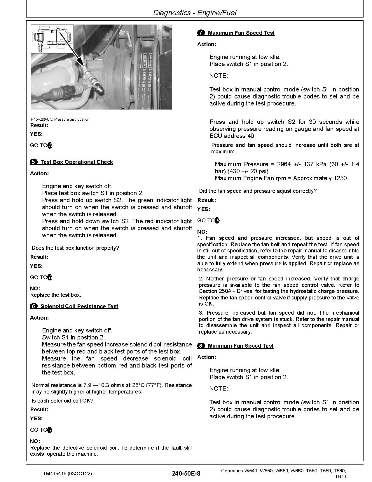
Diagnostics – Engine/Fuel
Diagnostics – Starting/Charging/Power Distribution
Diagnostics – Header Functions – Model Year 20 Headers and Older
Diagnostics – Header Functions – Model Year 21 Headers and Newer
Diagnostics – Feeder House
Diagnostics – Threshing/Separating/Cleaning
Diagnostics – Grain Tank/Unloading
Diagnostics – Residue System
Diagnostics – Transmission/Ground Drive Systems
Diagnostics – Hydraulic Oil/Pressure
Diagnostics – Main Gearcase
Diagnostics – Brakes
Diagnostics – Chassis
Electrical Control Units
General Information
Accessing Diagnostic Trouble Codes and Addresses
Theory of Operation
Schematics
Diagnostics
Automatic Temperature Control Unit Addresses ATC
Control Unit CAB Addresses CAB
Cab Switch Module Addresses CSM
Communications Unit Radio DE7
Engine Control Unit Addresses ECU
Grain Loss Monitor Control Unit Addresses GLM
Harvest Monitoring Module Addresses HMM
Control Unit JDL MTG Addresses JDL
Control Unit LC1 Addresses LC1
Control Unit LC2 Addresses LC2
Multi-function Lever Addresses MHC
Primary Display Unit Addresses PDU
Control Unit PTP Addresses PTP
Control Unit RC1 Addresses RC1
Control Unit SFC Addresses SFC
Steering Control Unit Addresses SSU
Secondary Display Unit Addresses VTI
Wireless Data Server Addresses WDS
Electrical Connector/Components
Electrical Connector/Components – Summary of References
General Information
XA – Electrical Assemblies
XB – Sensors
XE – Lights
XF – Fuses
XG – Charging
XH – Monitoring Devices
XK – Relays
XM – Motors
XR – Resistors
XS – Switches
XD – Diodes
XX/GND – Interconnects and Ground Points
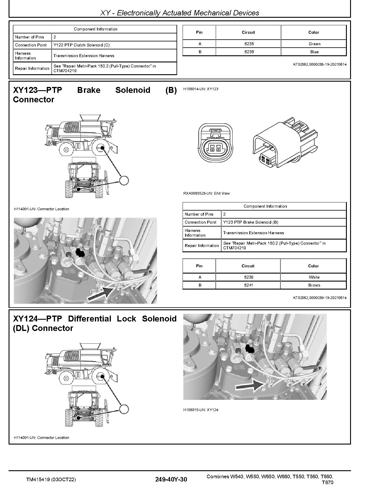
XY – Electronically Actuated Mechanical Devices
Header Model BP- Connectors
Header Model RD-F – Connectors
Header Model C-F C-R – Connectors
Drives
General Information
Preliminary and Operational Checks
Specifications
Theory of Operation
Schematics
Diagnostic Tests and Adjustments
Drives – Components
Drives – Components – Summary of References
Steering and Brakes
General Information
Preliminary and Operational Checks
Specifications
Theory of Operation
Schematics
Diagnostic Tests and Adjustments
Steering and Brakes – Components
Steering and Brakes – Components – Summary of References
Hydraulic System
General Information
Preliminary and Operational Checks
Specifications
Theory of Operation
Schematics
Diagnostics
Flex Draper Header Hydraulics – 600FD 700FD
Preliminary and Operational Checks
Hydraulic Specifications
Theory of Operation
Schematics
Diagnostics
Flex Cutterbar Auger Header Hydraulics – 600F
Preliminary and Operational Checks
Hydraulic Specifications
Theory of Operation
Schematics
Diagnostics
Rigid Draper Header Hydraulics – 600D 700D
Preliminary and Operational Checks
Hydraulic Specifications
Theory of Operation
Schematics
Diagnostics
Belt Pickup Header Hydraulics – 615P
Preliminary and Operational Checks
Hydraulic Specifications
Theory of Operation
Schematics
Diagnostics
Extendable Table Header Hydraulics – Narrow Feed 600X-700X
Preliminary and Operational Checks
Hydraulic Specifications
Theory of Operation
Schematics
Diagnostics
Rigid Cutterbar Auger Header Hydraulics – 600R
Preliminary and Operational Checks
Hydraulic Specifications
Theory of Operation
Schematics
Diagnostics
C-R Rigid Corn Header
Preliminary and Operational Checks
Hydraulic Specifications
Theory of Operation
Schematics
Diagnostics
RD-F Rigid Draper-Flex Knife Header
Preliminary and Operational Checks
Hydraulic Specifications
Theory of Operation
Schematics
Diagnostics
BP15 Belt Pick-up Header
Preliminary and Operational Checks
Hydraulic Specifications
Theory of Operation
Schematics
Diagnostics
Hydraulics – Components
Hydraulic – Components – Summary of References
Accumulator
Sensor or Gauge
Cylinder Actuator or Piston
Check Valve
Filter
Valve Block Assembly or Gear Case
Cooler
Motor
Orifice
Pump
Reservoir or Tank
Switch
Valve
Mechanical Assembly
Diagnostic Receptacle or Coupler
Solenoid Valve
Main Gear Case
General Information
Preliminary and Operational Checks
Specifications
Theory of Operation
Schematics
Diagnostic Tests and Adjustments
Main Gear Case – Components
Main Gear Case – Components – Summary of References
Cab/Open Operator`s Station
Specifications
Theory of Operation
Schematics
Diagnostics
Cab/Open Operator`s Station – Components
Cab/Open Operator`s Station – Summary of References
Cab/Open Operator`s Station – Components
Tools
General Information
Safety – Test Equipment
Diagnostic Trouble Code – Test Equipment
Electrical Systems – Test Equipment
Hydraulic Systems – Test Equipment
Cab/Operator Station – Test Equipment
Section 270E
Section 270F
Section 270G
Section 270H
Section 270I
Section 270J
Section 270K
Section 270M
Section 270N
Related Products
-
John Deere WL53 4WD Loaders Operation Test Manual TM14286X19
80 USDFormat: PDFLanguage: EnglishBrand: John DeereType of Manual: Operation Test ManualType of Machine: 4WD Wheeled LoaderModel: WL53Serial Number: 100080-Parts Number: TM14286X19
REALEASE :
REALEASE :
-
John Deere WL56 4WD Loaders Operation Test Manual TM14283X19
80 USDFormat: PDFLanguage: EnglishBrand: John DeereType of Manual: Operation Test ManualType of Machine: 4WD Wheeled LoaderModel: WL56Serial Number: 000326-Parts Number: TM14283X19
REALEASE :
REALEASE :
-
John Deere WL56 4WD Loaders Repair Manual TM12745
80 USDFormat: PDFLanguage: EnglishBrand: John DeereType of Manual: Repair ManualType of Machine: 4WD Wheeled LoaderModel: WL56Serial Number: 000010-000508 000326-000508Parts Number: TM12745
REALEASE :
REALEASE :
-
John Deere WL56 4WD Loaders Operation Test Manual TM12741
150 USDFormat: PDFLanguage: EnglishBrand: John DeereType of Manual: Operation Test ManualType of Machine: 4WD Wheeled LoaderModel: WL56Serial Number: 000010-000508 000326-000508Parts Number: TM12741
REALEASE :
REALEASE :
-
John Deere WL56 4WD Loaders Repair Manual TM14284X19
50 USDFormat: PDFLanguage: EnglishBrand: John DeereType of Manual: Repair ManualType of Machine: 4WD Wheeled LoaderModel: WL56Serial Number: 000509-Parts Number: TM14284X19
REALEASE :
REALEASE :
-
John Deere Windrowers 2320 2420 Technical Manual TM1224
30 USDSize: 56.27 MBFormat: PDFLanguage: EnglishBrand: John DeereType of Machine: WindrowersType of Manual: Technical ManualModel: John Deere 2320 2420 WindrowersPart Number: TM1224Number of Pages: 666 Pages
REALEASE :
REALEASE :
-
John Deere WL53 4WD Loaders Repair Manual TM13256X19
50 USDFormat: PDFLanguage: EnglishBrand: John DeereType of Manual: Repair ManualType of Machine: 4WD Wheeled LoaderModel: WL53Serial Number: 100008-100079Parts Number: TM13256X19
REALEASE :
REALEASE :
-
John Deere WL53 4WD Loaders Repair Manual TM14287X19
50 USDFormat: PDFLanguage: EnglishBrand: John DeereType of Manual: Repair ManualType of Machine: 4WD Wheeled LoaderModel: WL53Serial Number: 100080-Parts Number: TM14287X19
REALEASE :
REALEASE :