
0 ITEMSVIEW CART


✓
Expert Support
✓
Full Speed
✓
100% Working
John Deere T550 T560 T660 T670 W540 W550 W650 W660 Combines Diagnostic Manual TM406119
Format: PDF
Language: English
Brand: John Deere
Type Of Manual: Diagnostic Manual
Type of Machine: Combine
Model: John Deere T550 T560 T660 T670 W540 W550 W650 W660 Combine
Year: 2014 2015
Part Number: TM406119
300 USD
- Description
Description
Contents:
Introduction
Foreword
General
Safety
Combine and Component Identification
Standard Torque Values
Specifications
Diagnostic Trouble Codes
Accessing Diagnostic Trouble Codes and Addresses
ATC – Diagnostic Trouble Codes
CAB – Diagnostic Trouble Codes
CRU – Diagnostic Trouble Codes
CSM – Diagnostic Trouble Codes
ECU Levels 21 and 22 – iT4 Engines – Diagnostic Trouble Codes
ECU – Non-iT4 Engines – Diagnostic Trouble Codes
GLM – Diagnostic Trouble Codes
HMM – Diagnostic Trouble Codes
JDL – Diagnostic Trouble Codes
LC1 – Diagnostic Trouble Codes
LC2 – Diagnostic Trouble Codes
MHC – Diagnostic Trouble Codes
PDU – Diagnostic Trouble Codes
PTP – Diagnostic Trouble Codes
RC1 – Diagnostic Trouble Codes
SCL – Diagnostic Trouble Codes
SFC – Diagnostic Trouble Codes
SSU – Diagnostic Trouble Codes
VCM – Diagnostic Trouble Codes
VTi – Diagnostic Trouble Codes
WDS – Diagnostic Trouble Codes
Observable Symptoms
Engine System
Air Intake and Cooling Systems
Electrical System
Electrical Control Units
Drives
Steering and Brakes
Hydraulic System
Main Gearcase
Cab-Open Operator Station
Engine System
Engine System
Air Intake and Cooling System
Theory of Operation
Schematics
Air Intake and Cooling System – Components
Air Intake and Cooling System – Components – Summary of References
A Components
D Components
F Components
H Components
P Components
R Components
S Components
V Components
Electrical System
General Information
General References
Calibration Procedures
Theory of Operation – Cab/Operator`s Station
Theory of Operation – CAN Bus/Local Link Systems
Theory of Operation – Ag Management Solutions
Theory of Operation – Lighting
Theory of Operation – Engine/Fuel
Theory of Operation – Starting/Charging/Power Distribution
Theory of Operation – Header Functions
Theory of Operation – Feeder House
Theory of Operation – Threshing/Separating/Cleaning
Theory of Operation – Grain Tank/Unloading
Theory of Operation – Residue System
Theory of Operation – Transmission/Ground Drive Systems
Theory of Operation – Hydraulic Oil/Pressure
Theory of Operation – Main Gearcase
Theory of Operation – Brakes
Theory of Operation – Chassis
Schematics – Cab/Operator`s Station
Schematics – CAN Bus/Local Link Systems
Schematics – Ag Management Solutions
Schematics – Lighting
Schematics – Engine and Fuel
Schematics – Starting/Charging/Power Distribution
Schematics – Header Functions
Schematics – Feeder House
Schematics – Threshing/Separating/Cleaning
Schematics – Grain Tank/Unloading
Schematics – Residue System
Schematics – Transmission/Ground Drive Systems
Schematics – Hydraulic Oil/Pressure
Schematics – Main Gearcase
Schematics – Brakes
Schematics – Chassis
Diagnostics – Cab/Operator`s Station
Diagnostics – CAN Bus/Local Link Systems
Diagnostics – Ag Management Solutions
Diagnostics – Lighting
Diagnostics – Engine/Fuel
Diagnostics – Starting/Charging/Power Distribution
Diagnostics – Header Functions
Diagnostics – Feeder House
Diagnostics – Threshing/Separating/Cleaning
Diagnostics – Grain Tank/Unloading
Diagnostics – Residue System
Diagnostics – Transmission/Ground Drive Systems
Diagnostics – Hydraulic Oil/Pressure
Diagnostics – Main Gearcase
Diagnostics – Brakes
Diagnostics – Chassis
Electrical Control Units
Electrical Control Units – Summary of References
Accessing Diagnostic Trouble Codes and Addresses
Diagnostic Addresses by Control Unit
Theory of Operation
Schematics
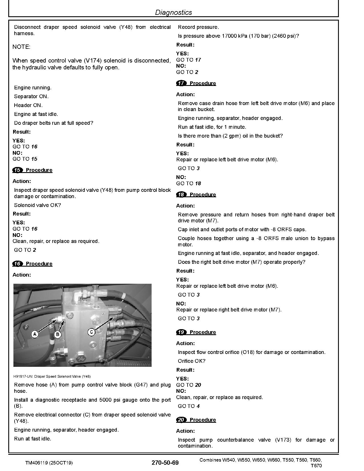
Diagnostics
Electrical Connector/Components
Electrical – Components – Summary of References
General Information
X100 – X149
X150 – X199
X200 – X249
X250 – X299
X300 – X349
X350 – X399
X400 – X449
X450 – X499
X500 – X549
X550 – X599
X600 – X649
X650 – X699
X700 – X749
X750 – X799
X800 – X849
X850 – X899
X900 – X949
X950 – X999
X1000 – X1049
X4000 – X4999
X5000 – X5999
X8000 – X8999
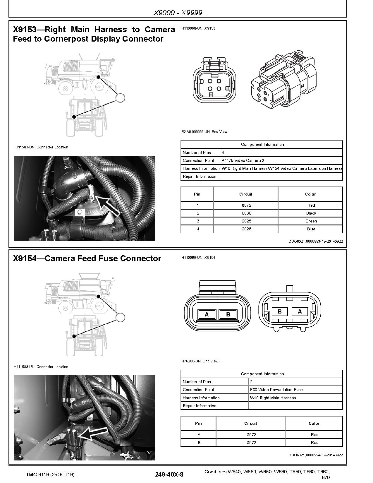
X9000 – X9999
Drives
Preliminary and Operational Checks
Specifications
Theory of Operation
Schematics
Diagnostics
Drives – Components
Drives – Components
Steering and Brakes
Preliminary and Operational Checks
Specifications
Theory of Operation
Schematics
Diagnostics
Steering and Brakes – Components
Steering and Brakes – Components – Summary of References
Hydraulic System
Preliminary and Operational Checks
Specifications
Theory of Operation
Schematics
Diagnostics
Hydraulic – Components
Hydraulic – Components – Summary of References
Hydraulic – A Components
Hydraulic – B Components
Hydraulic – C Components
Hydraulic – D Components
Hydraulic – F Components
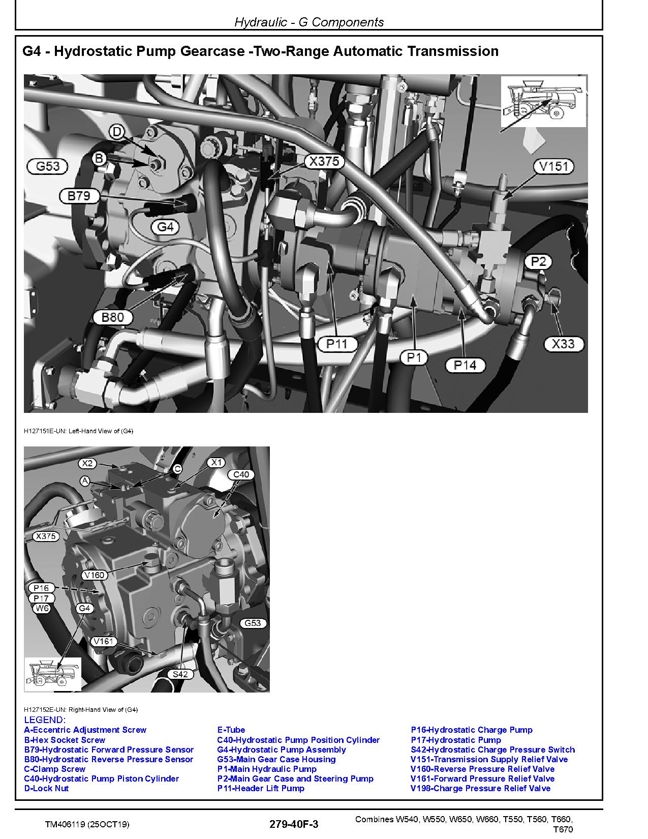
Hydraulic – G Components
Hydraulic – H Components
Hydraulic – M Components
Hydraulic – O Components
Hydraulic – P Components
Hydraulic – R Components
Hydraulic – S Components
Hydraulic – V Components
Hydraulic – W Components
Hydraulic – X Components
Hydraulic – Y Components
Main Gearcase
Preliminary & Operational Checks
Specifications
Theory of Operation
Schematics
Diagnostics
Main Gearcase – Components
Main Gearcase – Components – Summary of References
Cab/Open Operator`s Station
Specifications
Theory of Operation
Schematics
Diagnostics
Cab/Open Operator`s Station – Components
Cab/Open Operator`s Station – Summary of References
Cab/Open Operator`s Station – Components
Related Products
-
John Deere WL56 4WD Loaders Repair Manual TM12745
80 USDFormat: PDFLanguage: EnglishBrand: John DeereType of Manual: Repair ManualType of Machine: 4WD Wheeled LoaderModel: WL56Serial Number: 000010-000508 000326-000508Parts Number: TM12745
REALEASE :
REALEASE :
-
John Deere WL56 4WD Loaders Operation Test Manual TM14283X19
80 USDFormat: PDFLanguage: EnglishBrand: John DeereType of Manual: Operation Test ManualType of Machine: 4WD Wheeled LoaderModel: WL56Serial Number: 000326-Parts Number: TM14283X19
REALEASE :
REALEASE :
-
John Deere WL56 4WD Loaders Repair Manual TM14284X19
50 USDFormat: PDFLanguage: EnglishBrand: John DeereType of Manual: Repair ManualType of Machine: 4WD Wheeled LoaderModel: WL56Serial Number: 000509-Parts Number: TM14284X19
REALEASE :
REALEASE :
-
John Deere Windrowers 2320 2420 Technical Manual TM1224
30 USDSize: 56.27 MBFormat: PDFLanguage: EnglishBrand: John DeereType of Machine: WindrowersType of Manual: Technical ManualModel: John Deere 2320 2420 WindrowersPart Number: TM1224Number of Pages: 666 Pages
REALEASE :
REALEASE :
-
John Deere WL53 4WD Loaders Repair Manual TM13256X19
50 USDFormat: PDFLanguage: EnglishBrand: John DeereType of Manual: Repair ManualType of Machine: 4WD Wheeled LoaderModel: WL53Serial Number: 100008-100079Parts Number: TM13256X19
REALEASE :
REALEASE :
-
John Deere WL53 4WD Loaders Operation Test Manual TM14286X19
80 USDFormat: PDFLanguage: EnglishBrand: John DeereType of Manual: Operation Test ManualType of Machine: 4WD Wheeled LoaderModel: WL53Serial Number: 100080-Parts Number: TM14286X19
REALEASE :
REALEASE :
-
John Deere WL53 4WD Loaders Repair Manual TM14287X19
50 USDFormat: PDFLanguage: EnglishBrand: John DeereType of Manual: Repair ManualType of Machine: 4WD Wheeled LoaderModel: WL53Serial Number: 100080-Parts Number: TM14287X19
REALEASE :
REALEASE :
-
John Deere WL56 4WD Loaders Operation Test Manual TM12741
150 USDFormat: PDFLanguage: EnglishBrand: John DeereType of Manual: Operation Test ManualType of Machine: 4WD Wheeled LoaderModel: WL56Serial Number: 000010-000508 000326-000508Parts Number: TM12741
REALEASE :
REALEASE :