
0 ITEMSVIEW CART

✓
Expert Support
✓
Full Speed
✓
100% Working
Komatsu Forklift AE50 AM50 Series Service Manual SM152
Size: 28.91 MB
Format: PDF
Language: English
Brand: Komatsu
Type of Machine: Forklift
Type of Manual: Service Manual
Model: Komatsu AE50 AM50 Series Forklift
AE50: FB15U-12, FB18U-12, FB15FU-12, FB18FU-12, FB20AU-12, FB20AFU-12 S/N 837898~
AM50; FB15MU-12, FB18MU-12, FB15MFU-12, FB18MFU-12, FB20MU-12, FB20MFU-12 S/N 826828~
Part Number: SM152
Publication Date: 2010
Number of Pages: 394 Pages
20 USD
- Description
Description
Contents:
CONTENTS
- Specifications and General Information
Outside view
SPECIFICATIONS
PERIODIC REPLACEMENT OF CONSUMABLE PARTS
STANDARD TIGHTENING TORQUE FOR BOLTS
STANDARD TIGHTENING TORQUE FOR PIPE JOINTS
HOW TO USE LOCTITE
SAFETY
FIRE PREVENTION
BASIC PRECAUTIONS
START-UP INSPECTION
TRAVELING THE LIFT TRUCK
LOAD HANDLING OPERATION
PRECAUTIONS FOR INSPECTION AND MAINTENANCE
HOISTING AND TRANSPORTING THE LIFT TRUCK
STRUCTURE AND STABILITY OF THE LIFT TRUCK - Testing and Adjusting
Service Data (4-wheel lift truck)
Service Data (3-wheel lift truck)
releasing the pressure in the hydraulic piping
Lift Interrupt
Meter Panel
Operation of Meter Panel
Battery
Fuse
Transfer Case
Adjustment of Wet Type Brake and Parking Brake
Wet Type Brake
Hydraulic Oil Tank
Mast (1.5 – 1.75 ton lift truck)
Mast (2.0 ton lift truck)
Finger Bar
Naturally descending amount of hydraulic oil cylinder
Air Bleeding
List of Lubricant and Grease - Removal and Installation
Unit Location Diagram
Unit Mass (4-wheel lift truck)
Unit Mass (3-wheel lift truck)
Drawing of Disassembly/Assembly
Mast
Lift Cylinder
Drive Axle
Steering Axle
Rear Axle
Battery
Hydraulic Pump AND Pump Motor - Disassembly and Assembly
Drive Axle
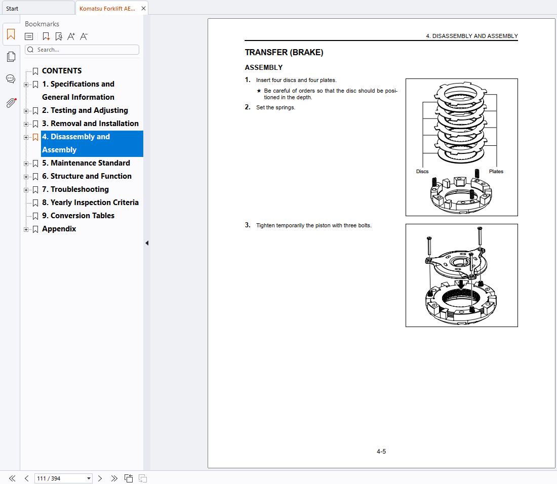
Transfer (Brake)
Transfer (hub bearing)
Transfer (Transfer)
Brake Wheel Cylinder
Brake Master Cylinder
Steering Gear Box
Orbitrol
Power Steering Cylinder (4-wheel lift truck)
Steering Axle (3-wheel lift truck)
Rear Axle (4-wheel lift truck)
Lift Cylinder
Tilt Cylinder
Hydraulic Pump
Control Valve
Drive Motor
Pump Motor - Maintenance Standard
Drive Axle
Wheel Cylinder Block
Brake Master Cylinder
Steering Axle (3-wheel lift truck)
Rear Axle
Lift Cylinder
Tilt Cylinder
Control Valve
HYDRAULIC PUMP
Mast, Finger Bar, Fork
Drive Motor
Pump Motor - Structure and Function
Brake
Hydraulic Circuit Diagram
Control Valve - Troubleshooting
Diagnosis Tool
Configuration Parts, Sensor, Unit Location Drawing
Location Drawing
Location of CPU Board Connector
Overview of Trouble CodeS
Preparation for voltage check and current check
Input / Output Signal of Controller
Trouble Code List
Diagnostic Procedure by Trouble Code (ALA code)
Diagnosis Procedure by trouble code (ERR code)
Diagnostic Procedure by Meter Display Trouble Code
Trouble without ERROR CODES
Proportional Solenoid Valve Controller
Adjustment Procedure of Tilt Automatic Horizontal
Meter Panel
HARNESS LIST - Yearly Inspection Criteria
- Conversion Tables
Appendix
3BA-97-99710 (Input Gear/Bearing Press-fitting Jig)
3BA-97-99720 (Multiple Disc Alignment Jig)
3BA-97-99730 (Multiple Holder Clearance Aligning Jig)
3BA-97-99740 (3-Wheel Rear Axle Press-fitting Jig)
3BA-97-99760 (3-Wheel Rear Axle Sensor Alignment Jig)
Service Tool Configuration
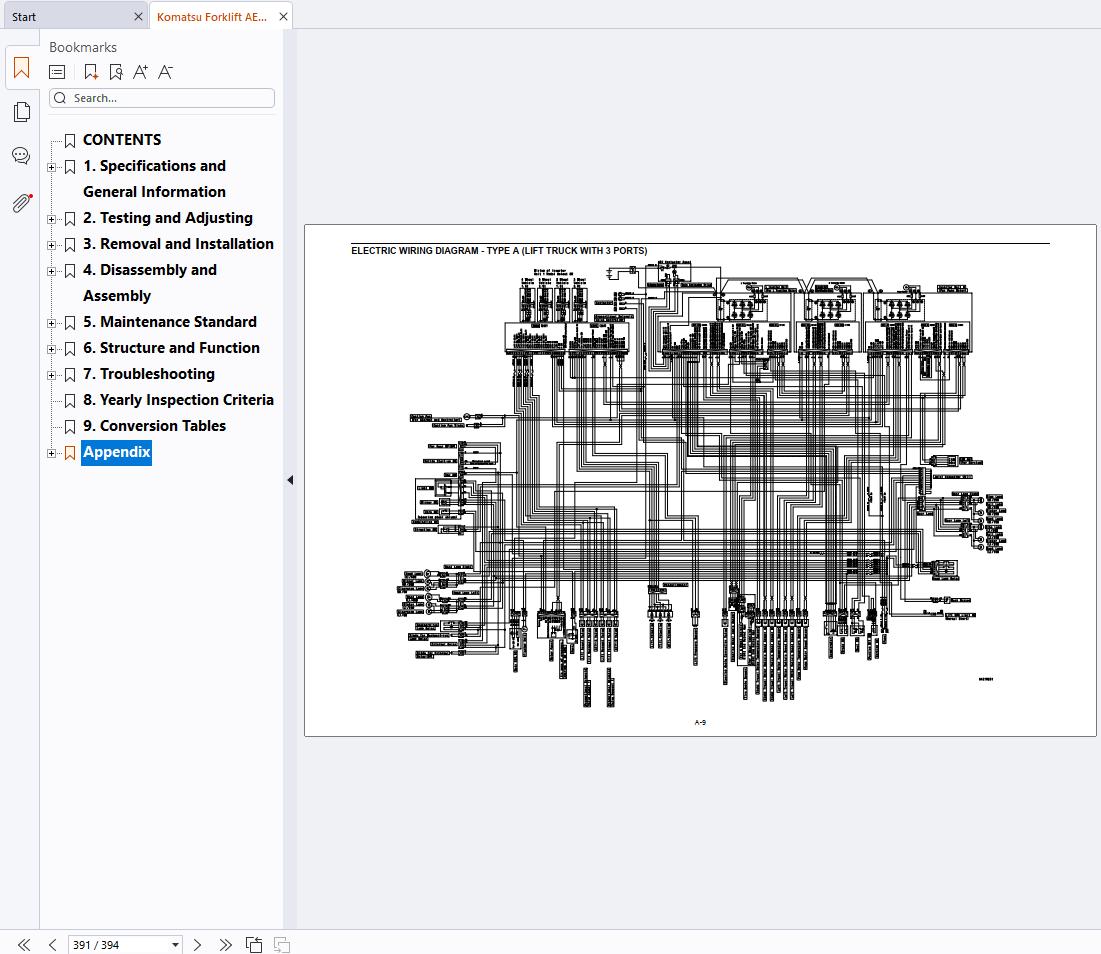
ELECTRIC WIRING DIAGRAM – TYPE A (lift truck WITH 3 ports)
ELECTRIC WIRING DIAGRAM – TYPE B (lift truck WITH 4 ports)
Related Products
-
Komatsu Service Manuals Forklift Class 1-5 PDF 2.48GB
Original price was: 200.150Current price is: 150. USDThis is a service information package, you will need to use this to repair a vehicleHot-25%
REALEASE :
REALEASE :
-
Komatsu Forklift Shop Manual Update 2024 9.41 GB PDF
250 USDSize: 9.41 GBLanguages: EnglishFormat: PDFBrand: KomatsuTypes of Document: Shop ManualTypes of Vehicle: ForkliftUpdated: 2024Hot
REALEASE :
REALEASE :
-
Komatsu Forklift Truck 3,1GB PDF DVD Part Manual, Shop Manual, Operation & Maintenance Manual
Original price was: 200.80Current price is: 80. USDKomatsu Forklift Truck 3,1GB PDF DVD Part Manual, Shop Manual, Operation & Maintenance ManualSize : 3.1 GBFormat : PDFLanguage : EnglishBrand: KomatsuType of machine: Komatsu ForkliftType of document: Part Manual, Shop Manual, Operation & Maintenance ManualHot-60%
REALEASE :
02.04.2021
REALEASE :
02.04.2021
-
Komatsu Forklift Operation Maintenance Manual 2024 2.0 GB PDF
150 USDSize: 2.0 GBLanguages: EnglishFormat: PDFBrand: KomatsuTypes of Document: Operation & Maintenance ManualTypes of Vehicle: ForkliftUpdated: 2024Hot
REALEASE :
REALEASE :
-
Komatsu Forklift FG20-11 FD25-11 FD30-11 Parts Book PEB11C1-05
15 USDSize: 3.08 MBFormat: PDFLanguage: EnglishBrand: KomatsuType of Machine: ForkliftType of Manual: Parts ManualModel: Komatsu ForkliftFG20-11, FG25-11, FG30-11FG20S-11, FG25S-11, FG30S-11FG30G-11, FG30SG-11FD25-11, FD30-11, FD25S-11Serial Number:FG20/25/30 -450050A and upFG20S/25S/30S -400001A and upFG30G -490001A and upFG30SG -490002A and upFD25/30 -430175A and upFD25S -480001A and upPart Number: PEB11Cl-05Publication Date: 1993Number of Pages: 155 Pages
REALEASE :
REALEASE :
-
Komatsu log Loaders 2022 Shop Manual Electrical Hydraulic Circuit Diagram PDF DVD
Original price was: 200.80Current price is: 80. USDKomatsu log Loaders 2022 PDF Shop Manual & Electrical & Hydraulic Circuit DiagramSize: 512 MbLanguages: EnglishFormat: PDFBrand: KomatsuTypes of Vehicle: Komatsu log LoadersQuantity of CD: 1 DVDUpdated: 2022Window: Window XP, Window 7, Window 8, Window 10 32 & 64bit, MAC OSHigh-Speed link DownloadHot-60%
REALEASE :
07.06.2022
REALEASE :
07.06.2022
-
Komatsu Forklift Shop Manual Updated 2022
Original price was: 400.200Current price is: 200. USDKomatsu Forklift 11.6 GB PDF Updated 2022 All Model Shop Manuals, Service Manual DVDSize: 11.6 GbLanguages: EN (English)Format: PDFBrand: Komatsu ForkliftQuantity of CD: 1 DVDUpdated: 2022OS: Window XP, Window 7, Window 8, Window 10 32 & 64bitHigh-Speed link DownloadDETAIL CONTENTS: “CLICK HERE“Hot-50%
REALEASE :
25.03.2022
REALEASE :
25.03.2022
-
Komatsu Forklift Truck 3,9GB PDF 2021 Part Manual, Shop Manual, Operation & Maintenance Manual DVD
Original price was: 250.150Current price is: 150. USDKomatsu Forklift Truck 3,9GB PDF 2021 Part Manual, Shop Manual, Operation & Maintenance Manual DVDSize : 3.94 GBFormat : PDFLanguage : EnglishBrand: KomatsuType of machine: Komatsu ForkliftType of document: Part Manual, Shop Manual, Operation & Maintenance ManualHot-40%
REALEASE :
26.06.2021
REALEASE :
26.06.2021