
9 ITEMSVIEW CART


Total: 1,110.00


Expert Support
Full Speed
100% Working
100 USD
Contents:
1 General Aspects
1.1 Safety
1.1.1 Safety Instructions and Accident Prevention Regulations
1.2 Tightening Torques
1.3 Technical Data
1.4 Tyre Pressure Table
1.5 Welding on the Vehicle
1.6 Towing the Machine
1.7 Machine Overview
1.7.1 Overview of Crop Flow and Speeds
1.8 Front Attachments
2 Mechanical Drives
2.1 Removing and Installing
the Main Coupling
2.1.1 Removing and Installing the Main Coupling
2.1.1.1 Removing and Installing the Cylinder of the Main Coupling
2.1.1.2 Removing and Installing the Cylinder of the Main Coupling
2.1.1.3 Replacing Blades of the Main Coupling
2.2 Removing and Installing the Power Take-off Gear
2.2.1 Removing the Centre Max Coupling
2.2.2 Replacing the Shaft Sealing Ring on the Gear Input Shaft
2.2.3 Replacing the Shaft Sealing Ring on the Gear Output Shaft
2.3 Removing and Installing the Transfer Gearbox
2.3.1 Replacing the Shaft Sealing Rings of the Gear Output Shafts
2.4 Removing and Installing the Upper Discharge Chute
Rotating Drive
2.4.1 Adjusting the Edge Play on the
Tower Gearbox
2.5 Radiator Fan
2.5.1 Removing and Installing the Radiator Fan
2.5.2 Removing and Installing the Fan Gear
2.6 Removing and Installing the Main Belt Tensioning System
2.7 Removing and Installing the Main V-Belt
2.7.1 Adjusting the Main V-Belt
2.8 Replacing the Suction Fan V-Belt
2.9 Changing the Fan V-Belt
2.10 Changing the Compressed Air Compressor V-Belt (V12 and V8 to year of manf. 2005 only)
2.11 Replacing the Air Conditioner Compressor V-Belt
2.12 Changing the V-Belt of the Generator (V8)
2.13 Changing the V-Belt of the Generator (V12)
2.14 Changing the V-Belt of the Additional Generator (V12)
2.15 Replacing the V-Belt of the Grain Conditioner
2.15.1 Adjusting the V-Belt of the Grain Conditioner
3 Components for Crop Flow
3.1 Pre-compression Unit
3.1.1 Removing and Installing the Pre-Compression Unit
3.1.1.1 Removing the Pre-Compression Unit with Front Attachment
3.1.1.2 Removing the Pre-Compression Unit without Front Attachment with Installation Cart
3.1.2 Removing and Installing the Pre-Compression Unit Cover
3.1.3 Removing and Installing the Upper Roller Unit
3.1.3.1 Adjusting the Baling Roller – Scraper
3.1.3.2 Adjusting the Tension Springs of the Feed Drive Housing
3.1.5 Removing and Installing the Lower Roller Gearbox
3.1.5.1 Replacing the Shaft Sealing Rings on the Lower Roller Gearbox
3.1.6 Removing and Installing the Lower Roller Unit
3.1.6.1 Adjusting Scraper – Smooth Roller
3.1.7 Removing and Installing the Lower Pre-Compression Roller and Smooth Roller
3.1.8 Removing and Installing the Metal Detection System
3.1.9 Removing and Installing the Bearing Plate
3.1.10 Removing and Installing the Upper Pre-Compression Rollers and Feed Drive Roller
3.1.10.1 Replace Inner Shaft Sealing Rings on Upper Roller Gearbox
3.1.10.2 Replacing the Outer Shaft Sealing Rings on the Upper Roller Gearbox
3.1.11 Removing/Installing the Rollers of the Upper Roller Unit
3.2 Blade Drum
3.2.1 Replacing the Cutting Blade
3.2.1.1 Adjusting the Counterblade According to the Grinding Pattern
3.2.2 Removing, Installing, and Turning the Counterblade
3.2.3 Removing and Installing the Cutting Drum Housing including Blade Drum
3.2.3.1 Removing and Installing the Blade Drum
3.2.3.2 Dismounting the Bearing Blocks of the Blade Drum
3.2.3.3 Mounting the Bearing Blocks of the Blade Drum
3.2.4 Removing and Installing the grinding device
3.2.4.1 Aligning the Grinding Device
3.2.4.2 Removing and Installing the Grinding Device
3.2.4.3 Readjusting or Replacing the Grinding Stone
3.2.5 Removing and Installing the Anvil
3.3 Transfer Channel
3.3.1 Replacing the Wear Plate in the Transfer Shaft
3.4 Grain Conditioner
3.4.1 Removing and Installing the Grain Conditioner Rollers
3.4.1.1 Replacing Roller Bearings
3.4.2 Checking and Adjusting the Distance of the Grain Conditioner Rollers.
3.4.3 Replacing the Wear Plates in the Grain Conditioner
3.5 Discharge Accelerator
3.5.1 Removing and Installing the Rear Wall of the Discharge Accelerator
3.5.2 Replacing the Discharge Scoops
3.5.3 Adjusting the Scraper
3.5.4 Replacing the Wear Plates
3.5.5 Adjusting the Distance of the Discharge Accelerator Rear Wall
3.5.6 Removing and Installing the Discharge Accelerator Bearing Block, Left
(Floating Bearing)
3.5.7 Removing and Installing the
Discharge Accelerator Bearing Housing, Right (Fixed Bearing)
3.5.8 Removing and Installing the Discharge Accelerator
3.5.8.1 Removing andMounting the Floating Bearing Block of the Discharge Accelerator III – 149
3.5.8.2 Removing and Mounting the Fixed Bearing Housing ofthe Discharge Accelerator III – 151
3.6 Tower
3.6.1 Removing and Installing the Tower
3.6.1.1 Removing and Installing the Tower
3.6.2 Turning the Slewing Ring
3.7 Upper Discharge Chute
3.7.1 Removing and Installing the Upper Discharge Chute
3.7.2 Connecting the Upper Discharge Chute Extension
3.7.3 Replacing the Wear Plates in the Upper Discharge Chute
4 Work Hydraulics
4.1 Work Hydraulics Diagnostics
4.1.1 Pressure Measurements
4.1.2 Measuring Connections for Feed/Front Attachment, Work, Brake and Steering
Hydraulics
4.2 Removing and Installing the Triple Gearwheel Pump
4.2.1 Removing and Installing the Triple Gearwheel Pump
4.2.1.1 Removing and Installing the Sieve Drive Pump
4.2.1.2 Removing and Installing the Pump for Work Hydraulics
4.2.1.3 Removing and Installing the Steering Pump
4.3 Brake Hydraulics
4.3.1 Replacing the Accumulator Charging Valve
4.3.2 Parking Brake
4.3.2.1 Replacing the Parking Brake Cylinder
4.3.2.2 Replacing the Parking Brake Valve
4.3.2.3 Replacing the Manometric Switch
4.3.3 Operating Brake
4.3.3.1 Replacing the Brake Valve
4.3.3.2 Replacing the Pressure Sensor
4.3.4 Bleeding the Brake System
4.4 Implement Hydraulics
4.4.1 Overview of Hydraulic Valves of the Work Hydraulics
4.4.2 Replacing the Pressure Limiting Valves (Work Hydraulics)
4.4.3 Removing and Installing the Control Disc (Directional Valve)
4.4.3.1 Replacing the Locking Block
4.4.4 Replacing the EHR
4.4.5 Setting the Throttle Valves
4.4.6 Replacing the Gras/Maize
Switching Valve
4.5 Steering Hydraulics
4.5.1 Replacing the Steering Unit
4.5.2 Replacing the Steering Pressure Sensor (optional with Autopilot)
4.5.3 Replacing the Double Non-Return Valve (Autopilot Option)
4.6 Sieve Drive
4.6.1 Replacing the Pressure Limiting Valve
4.6.2 Replacing the Sieve Drive Motor
4.7 Work Hydraulics Feed Drive/Front Attachment
4.7.1 Removing and Installing the Feed Drive and Front Attachment Pump
4.7.2 Replacing the Feed Drive / Front Attachment Motor
4.7.3 Removing and Installing the Quick-Stop Valve
4.7.3.1 Replacing the Pilot Valve
4.7.4 Removing and Installing the
Adjustment Unit on the Feed Drive and Front Attachment Pump
4.7.4.1 Replacing the Magnetic Coils of the Adjustment Unit
4.7.5 Removing and Installing the Charge Pressure Limiting Valves on the Feed Drive and
Front Attachment Pump
4.7.6 Removing and Installing the
Multifunction Valve on the Feed Drive and Front Attachment Pump
4.7.7 Removing and Installing the Filling Pressure Limiting Valves on the Feed Drive and
Front Attachment Motor
5 Driving Hydraulics
5.1 Driving Hydraulics Diagnostics
5.1.1 Measurements Connections of the Drive Hydraulics
5.2 Removing and Installing
the Drive Pumps
5.3 Replacing the Front Wheel Motors
5.4 Replacing the Rear Wheel Motors
5.5 Replacing the High-Pressure Sensor
5.6 Removing and Installing the Combination Valve, Complete
5.6.1 Removing and Installing All-Wheel Switching (Pilot Valve)
5.6.2 Removing and Installing Axle Separation (Pilot Valve)/Flush Valve
5.7 Absorption Volume Switching Valves
5.7.1 Replacing the Front Axle Switching Valve
5.7.2 Replacing the Rear Axle Switching Valve
5.8 Replacing the Pump Proportional Valves
5.9 Replacing the Charge Pressure Limiting Valves
5.10 Replacing the High Pressure Limiting Valves
6 Engine
6.1 Fuel System
6.1.1 Removing and Installing the Fuel Tank
6.1.2 Replacing the Immersion Pipe Sensor
6.1.3 Installing the Ascending Pipe
6.1.4 Removing and Installing the Fuel Additive Tank (Optional)
6.2 Removing and Installing the Engine
6.2.1 Removing and Installing the V8 Engine
6.3 Radiator
6.3.1 Replacing the Radiator Segment for Coolant/Hydraulic Oil
6.3.2 Replacing the Radiator Segment for Charge Air
6.3.3 Suction Fan
6.3.3.1 Removing and Installing the V8 Suction Fan
6.3.3.2 Removing and Installing the V12 Suction Fan
6.3.3.3 Removing and Installing the Suction Fan
7 Electrical System
7.1 General Aspects
7.1.1 Batteries
7.1.1.1 External Starting of the Machine
7.1.2 Lighting on the Machine
7.1.3 Generator
7.1.3.1 Replacing the Generator (V8)
7.1.3.2 Replacing Generators (V12)
7.1.3.3 Replacing the additional Generator (V12)
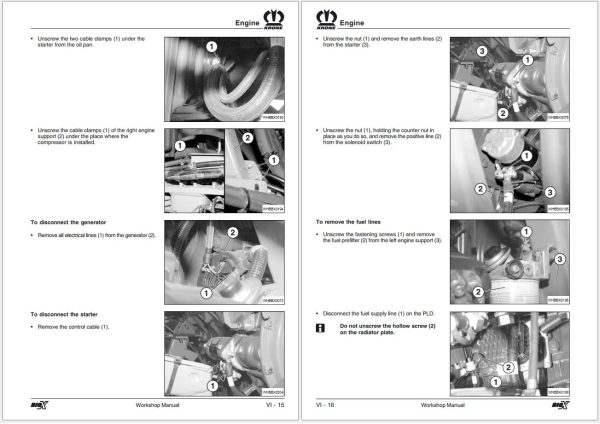
7.1.4 Starter
7.1.4.1 Replacing the Starter (V8)
7.1.4.2 Replacing the Starter (V12)
7.1.5 Replacing the main Battery Switch
7.1.6 Bus Bars
7.2 Diagnostics
7.2.1 Menu Guidance
7.2.1.1 Display Symbols
7.2.2 Function Tables
7.2.3 Information Messages
7.2.4 BiG X Error Messages
7.2.5 V8 Engine Error Codes
7.2.6 Diagnostics of the EMR Lifting Gear Control
7.2.7 Metal Detection Diagnostics
7.2.8 Diagnostics – Joystick Functions
7.2.9 Diagnostics – Panel Switches
7.2.10 Diagnostics – Panel Buttons
7.2.11 Manual Operation Diagnostics
7.2.12 Sensor Diagnostics
7.2.13 Actuator Diagnostics (Valve Diagnostics)
7.3 Subdistributors
7.3.1 Description of Plugs on the Subdistributors
7.3.1.1 Identification of Terminals on X3 Terminal Strips
7.3.2 Job Computers
7.3.2.1 Replacing the Job Computer
7.3.2.2 Replacing Software Memory Modules
7.3.2.3 Replacing the Back-up Battery in the Job Computer
7.3.2.4 Fitting Diagrams for Job Computers KMC2 and KMC3
7.3.3 SmartDrive
7.3.3.1 Replacing SmartDrive
7.3.4 Relay Boards
7.3.4.1 Replacing Relay Boards
7.3.4.2 Replacing the GAL Component
7.3.4.3 Fitting Diagram of Relay Board
7.4 Panel Computer
7.4.1 Description of Plugs on the Console
7.4.2 Removing the Panel Computer
7.5 Cabin Circuit Board
7.5.1 Replacing the Cabin Circuit Board
7.5.1.1 Fitting Diagram for Cabin Circuit Board
7.5.2 Designation of Plugs, Rear Wall of Cabin
7.6 Autopilot (optional)
7.6.1 Replacing the Autopilot Computer
7.7 DIOS Control (optional)
7.7.1 Replace DIOS Control
7.8 Hydraulic Terminal Box
7.8.1 Identification of Terminals on the Terminal Strip
7.9 Calibration
7.9.1 Calibration of the Pendulum Frame
7.9.2 Adjusting the Lifting Gear
7.9.3 Cutting Height Calibration
7.9.4 Front Attachment Calibration
7.9.5 Feed Drive Calibration
7.9.6 Corn Conditioner Calibration
7.9.7 Calibration route
7.9.7.1 Performing a calibration run (field mode with 2-wheel drive)
7.9.7.2 Performing a calibration run (field mode with all-wheel drive)
7.9.8 Calibration of the Upper Discharge Chute
7.9.9 Calibration of Autopilot
7.9.8.1 Functional Check of the Autopilot
7.10 CAN Bus
7.10.1 General Information
7.10.2 Diagnostics
7.10.3 Performing Measurements on the CAN Bus
7.11 Engine Electrical System
7.11.1 Replacing the ADM2 Control Unit (V8)
7.11.2 Replacing the PLD Control Unit (V8)
7.11.3 Engine Diagnosis using Minidiag 2 (V8)
7.11.3.1 Displaying System Information
7.11.3.2 Automatic Control Unit Detection
7.11.3.3 Displaying Control Unit Information
7.11.3.4 Display Fault Storage
7.11.3.5 Delete Fault Storage
7.11.3.6 Individual Parameter Assignment
7.11.3.7 Data Set Parameter Assignment
7.11.3.8 Saving the modified Programme Set
7.11.3.9 PLD Parameter List
7.11.4 Replacing the Heinzmann Controller (V12)
7.11.4.1 Calibrating the Control Rod with the HP 03-03 Hand Programmer (V12)
7.11.5 Engine Diagnostics with the HP 03-03 Hand Programmer (V12)
7.11.6 Overview of Sensors on the Engine (V8)
7.11.7 Overview of Sensors on the Engine (V12)
7.12 Joystick
7.12.1 Replacing the Joystick
7.13 Software
7.13.1 KRONE Download Center
7.13.1.1 Accessories Required for Software Update
7.13.1.2 Installing the KRONE Download Center
7.13.1.3 Performing a Software Update
7.13.2 Phases (Poclain Hydraulics) for SmartDrive
7.14 Fitting a Radio/CB Radio/Hands-Free Mobile Telephony Kit
7.15 Sensors
7.15.1 Error Types of Sensors
7.15.2 Sensors on the Machine
7.16 Parameters
7.16.1 Adjusting Parameters
7.16.2 Parameters of the BiG X
7.16.3 Parameter Diagrams
7.17 Repair Jobs on the Electrical System
7.17.1 Working with the Multimeter
7.17.2 Plug Repair
7.17.2.1 Deutsch Plug
7.17.2.2 AMP Plug, Various Sizes
7.17.2.3 Super Seal Plug
7.17.2.4 Cube Plug
7.17.2.5 Molex Plug (Large)
7.17.2.6 Molex Plug (Small)
7.17.2.7 Delphi Plug
7.17.2.8 Plug on the ADM2 Control Unit
8 Maintenance
8.1 Lubrication and Consumables Table
8.2 Engine
8.2.1 Replacing Engine Oil
8.2.1.1 Replacing the Oil Filter
8.2.2 Resetting the Service Interval
8.2.3 Replacing Coolant
8.2.4 Fuel System
8.2.5 Replacing the Air Filter Cartridge
8.3 Hydraulic System
8.3.1 Replacing Hydraulic Oil
8.3.1.1 Replacing Hydraulic Oil in the
Hydraulic Oil Tank
8.3.1.2 Replacing Hydraulic Oil Completely
8.3.1.3 Venting the Hydraulic System
8.3.1.4 Using Bio-Hydraulic Oils when Changing Hydraulic Oil
8.3.2 Replacing the Hydraulic Fluid Filter
8.4 Gearboxes
8.4.1 Power Take-off Gear, Oil Level Check and Oil Change
8.4.2 Transfer Gearbox, Oil Level Check and Oil Change
8.4.3 Upper Discharge Chute Rotating Drive, Oil Level Check and Oil Change
8.4.4 Fan Gear, Oil Level Check and Oil Change
8.4.5 Lower Roller Gearbox, Oil Level Check and Oil Change
8.4.6 Upper Roller Gearbox, Oil Level Check and Oil Change
8.5 Central Lubrication
8.5.1 Lubricant Filling
8.6 Compressed Air System
(V12 only)
8.6.1 Compressed air Compressor, Oil Level Check
8.6.2 Compressed Air Storage Tank
8.7 Air Conditioning System
8.7.1 Fresh Air Filter and Circulation filter
(Cab)
8.7.2 Collector/Dryer
8.7.3 Capacitor
8.7.4 Checking the Refrigerant Condition and the Filling Quantity
8.8 Battery
8.8.1 Checking the Acid Level
8.8.2 Measuring the Acid Density
8.9 Maintenance Schedule
9 Other Work
9.1 Steering Axle
9.1.1 Replacing the Steering Knuckles
9.1.2 Removing the Steering Cylinder
9.1.3 Replacing the Axial Track Rod
9.1.4 Measuring and Adjusting the Track
9.1.5 Adjusting the Steering Limit
9.1.6 Removing and Installing the Steering Axle
9.2 Steering Axle Swinging Arm
9.2.1 Removing and Installing the Spring Assembly and Steering Axle Swinging Arm
9.3 Operating brake
9.3.1 Replacing the Brake Lining and Adjusting the Brakes
9.4 Fitting Additional Weights
9.5 Removing and Installing the Side Plate and Tailgate
9.6 Removing and Installing the Mudguard
9.7 Removing and Installing the Driver’s Cab Roof
9.8 Grass <=> Maize Conversion
9.9 Central Lubrication
9.9.1 General Aspects
9.9.2 Electrical Connection
9.9.3 Programming
9.9.3.1 Changing the Interval of Lubrication
9.9.3.2 Changing System Monitoring
9.9.4 Operating Faults
9.10.5 Block Mode
9.9.6 Troubleshooting and Remedy of Error
9.9.6.1 Eliminating Blockages
9.9.6.2 Replacing the Central Lubrication Pump
9.9.6.3 Bleeding the System
9.10.6.4 Replacing the Pressure Limiting Valve
9.10.6.5 Replacing a Pump Element
9.9.6.6 Replacing the Cycle Switch
9.9.6.7 Removing and Installing the Progressive Distributor
9.10 Removing and Installing the Compressed Air Compressor V12
9.11 Retrofitting an Additional Tank
9.11.1 Retrofitting an Additional Tank as a Silage Agent Tank
9.11.2 Removing and Installing the Silage Agent Tank
9.11.3 Retrofitting the Additional Tank as a Fuel Tank
10 Air Conditioning System
10.1 Safety Regulations for Air Conditioning System
10.2 Basics
10.2.1 The Refrigerant Circuit
10.2.2 Technical Data
10.2.3 Tightening Torques on the Refrigerant Lines
10.3.1 Finding Leaks
10.3 Work on the Refrigerant Circuit
10.3.2 Replacing Components
10.3.3 Dehumidifying the Air Conditioning System
10.3.4 Refrigerant Oil
10.4 Air Conditioning System Diagnostics
10.4.1 Error Diagnostics of the Air Conditioning System
10.4.3 Pressure Test
10.4.2 Measuring the Cooling Performance of the Air Conditioning System
10.5 Suctioning Refrigerant out of the Air Conditioning System and Refilling
10.6 Rinsing the Air Conditioning System with Nitrogen
10.7 Replacing the Dryer/Collector Unit
10.7.1 Replacing the Manometric Switch
10.8 Replacing the Capacitor
10.9 Replacing the Compressor
10.10 Replacing the Heating Valve
10.11 Replacing the Evaporator
10.12 Replacing the Expansion Valve
A Appendix
A1 Special tool
A2 Index
REALEASE :
REALEASE :
REALEASE :
REALEASE :

REALEASE :
29.07.2022
REALEASE :
29.07.2022
REALEASE :
REALEASE :

REALEASE :
17.07.2021
REALEASE :
17.07.2021
REALEASE :
REALEASE :
REALEASE :
REALEASE :
REALEASE :
REALEASE :
 Automotive - Heavy Equipment - Truck & Bus - Forklift - Crane