
0 ITEMSVIEW CART

✓
Expert Support
✓
Full Speed
✓
100% Working
Kubota Excavator KX080-4a2 KX080-4S2 KX085-5 Diagnosis Manual RY910-27322 2023
Size: 15.46 MB
Format: PDF
Language: English
Brand: Kubota
Type of Machine: Excavator
Type of Manual: Diagnosis Manual
Model: Kubota KX080-4a2 KX080-4S2 KX085-5 Excavator
Engine: V3307-CR-TE5-BH-1
Part Number: RY910-27322
Publication Date: 2023
Number of Pages: 203 Pages
10 USD
- Description
Description
Contents:
1. Safety
Safety First
1. Working Precautions
2. Preparing For Emergencies
3. Working Cautions
4. Starting Machine Safely
5. Preventing Fires
6. Preventing Acid Burns
7. Avoiding High Pressure Fluid
8. Avoiding Hot Exhaust
9. Cleaning Exhaust Filter
2. Common Rail System
Mechanism
1. Basic System Information
1.1 System Configuration
1.2 Fuel System
1.3 Intake And Exhaust System
1.4 System Wiring Diagram
1.5 Available Data Monitor Signals (Level 4)
1.5.1 Monitor Items
1.5.2 Normal Value
1.6 Ecu Terminal Layout
1.6.1 Ecu Terminal Layout (Wire Harness Side)
Servicing
1. General
1.1 Overall Diagnostic Procedure
1.2 Questioning
1.2.1 Trouble Check Sheet For Kubota Common Rail System
1.3 List Of Malfunction Symptom
1.4 Actions For Non-Reoccurring Malfunctions
2. Diagnostic Tool Connection Procedure
2.1 Diagnostic Connector And Engine Ecu Positions
2.2 Diagnostic Tool Connection Procedure
2.3 Checking The Communication Operation Of The Interface (Dst-I)
2.3.1 Dst-I Operation Status And Display Specification
2.4 Checking The Operation Of The Ecu
2.4.1 Starting Diagmaster
2.4.2 Dst-I Communication Settings
2.4.3 Starting Kobd Ace
3. Diagnosis Functions
4. Diagnosis By Malfunction Symptom
4.1 List Of Malfunction Causes By Symptom
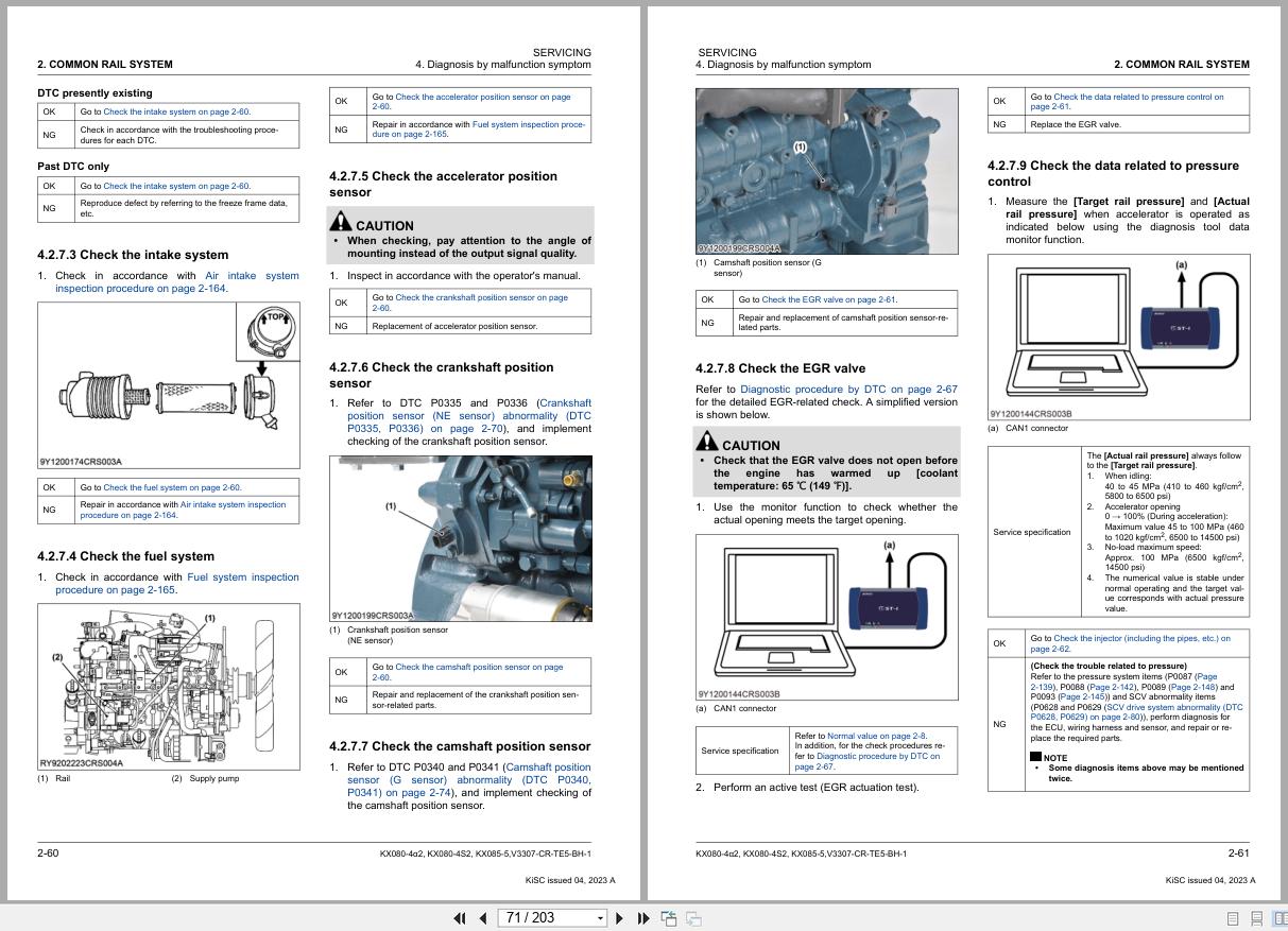
4.2 Diagnosis By Malfunction Symptom
4.2.1 Engine Does Not Start
4.2.2 Takes A Long Time Before Engine Starts
4.2.3 Idle Failure
4.2.4 Engine Noise
4.2.5 High Fuel Consumption
4.2.6 Insufficient Output
4.2.7 Abnormal Black Smoke Emitted
4.2.8 Abnormal White Smoke Emitted
5. Diagnostic Procedure By Dtc
5.1 Diagnostic Procedure By Dtc
5.1.2 Engine Overrun (Dtc P0219)
5.1.3 Crankshaft Position Sensor (Ne Sensor) Abnormality (Dtc P0335, P0336)
5.1.4 Camshaft Position Sensor (G Sensor) Abnormality (Dtc P0340, P0341)
5.1.5 Rail Pressure Sensor Abnormality (Dtc P0192, P0193)
5.1.6 Scv Drive System Abnormality (Dtc P0628, P0629)
5.1.7 Intake Air Temperature Error (Dtc P0112, P0113)
5.1.8 Coolant Temperature Sensor Abnormality (Dtc P0117, P0118)
5.1.9 Fuel Temperature Sensor Abnormality (Dtc P0182, P0183)
5.1.10 Injector Charge Voltage: High (Dtc P0200)
5.1.11 Open Circuit Of Harness-Coil (Dtc P0201, P0202, P0203, P0204)
5.1.12 Injector Charge Voltage Abnormality (Dtc P0611)
5.1.13 Common 1 System Injector Drive Circuit Open (Dtc P2146)
5.1.14 Common 1 Twv Actuation System Short (Dtc P2147, P2148)
5.1.15 Common 2 System Injector Drive Circuit Open (Dtc P2149)
5.1.16 Common 2 Twv Actuation System Short (Dtc P2150, P2151)
5.1.17 Boost Pressure Sensor Abnormality (Dtc P0237, P0238)
5.1.18 Battery Voltage Abnormality (Dtc P0562, P0563)
5.1.19 Sensor Supply Voltage 1 Abnormality (Dtc P0642, P0643)
5.1.20 Sensor Supply Voltage 2 Abnormality (Dtc P0652, P0653)
5.1.21 Main Relay Is Locked In Closed Position (Dtc P0687)
5.1.22 Barometric Pressure Sensor Error (Dtc P2228, P2229)
5.1.23 Egr Actuator Abnormality (Dtc P0403, Dtc P0404, P0409)
5.1.24 Egr (Dc Motor) Abnormality (Dtc P2413, P2414, P2415)
5.1.25 No Communication With Egr (Dtc U0076)
5.1.26 Engine Overheat (Dtc P0217)
5.1.27 Qr Data Abnormality (Dtc P0602)
5.1.28 Ecu Flash-Rom And Cpu Abnormality (Dtc P0605, P0606)
5.1.29 Accelerator Position Sensor Error (Can) (Dtc P2131)
5.1.30 Can2 Bus Off (Dtc U0075)
5.1.31 Can1 Bus Off (Dtc U0077)
5.1.32 Can2 Frame Error (Dtc U0081, U0082, U0083, U0087)
5.1.33 Intake Air Temperature Built-In Maf Sensor: Abnormality (Dtc P0072, P0073)
5.1.34 Maf Sensor Abnormality (Dtc P0102, P0103)
5.1.35 Intake Throttle Feedback Error (Dtc P2108)
5.1.36 Intake Throttle Lift Sensor Abnormality (Dtc P2621, P2622)
5.1.37 Differential Pressure Sensor 1 Abnormality (Dtc P2454, P2455)
5.1.38 Exhaust Gas Temperature Sensor 0 (T0) Abnormality (Dtc P0546, P0547)
5.1.39 Exhaust Gas Temperature Sensor 1 (T1) Abnormality (Dtc P0543, P0544)
5.1.40 Exhaust Gas Temperature Sensor 2 (T2) Abnormality (Dtc P242c, P242d)
5.1.41 All Exhaust Gas Temperature Sensor Failure (Dtc P3018)
5.1.42 Emission Deterioration (Dtc P3001)
5.1.43 Parked Regeneration Time Out (Dtc P3013)
5.1.44 Low Coolant Temperature In Parked Regeneration (Dtc P3012)
5.1.45 High Frequency Of Regeneration (Dtc P3024)
5.1.46 Pressure Limiter Emergency Open (Dtc P0087)
5.1.47 High Rail Pressure (Dtc P0088)
5.1.48 Fuel Leak (In High Pressured Fuel System) (Dtc P0093)
5.1.49 Scv Stuck (Dtc P0089)
5.1.50 Pump Seizing (Dtc P1274, P1275)
5.1.51 Intake Air Volume: Low (Dtc P0101)
5.1.52 Boost Pressure Low (Dtc P3011)
5.1.53 Exhaust Gas Temperature Sensor 0: Emergency High (Dtc P3002)
5.1.54 Exhaust Gas Temperature Sensor 1: Emergency High (Dtc P3003)
5.1.55 Exhaust Gas Temperature Sensor 2: Emergency High (Dtc P3004)
5.1.56 Continuous Abnormal Exhaust Gas Temperature Error (Dtc P3023)
5.1.57 Removal Of Dpf (Pcd) (Dtc P1a28)
5.1.58 Loss Of Function Of Dpf (Pcd) (Dtc P3015)
6.1 Air Intake System Inspection Procedure
6.1.1 Check The Air Cleaner
6.1.2 Check The Suction Path
6.2 Fuel System Inspection Procedure
6.2.1 Check The Fuel System (Remaining Fuel Quantity And Properties)
6.2.2 Check The Inside Of The Tank (Checking For Tank Modification – Additions, Position Of Fuel
Pipe Inlet – Outlet, Clogging And Holes)
6.2.3 Tank External Fuel Path Conditions (Crushed Hose, Clogging, Air Introduction At Hose
Connection)
6.2.4 Check The Water Separator
6.2.5 Check The Fuel Pump
6.2.6 Fuel Filter Clogged
6.2.7 Engine Oil Level Increase (Engine Internal Leak)
6.2.8 Check The High Pressure Piping And Crs Components (Such As The Fuel Injector And The
Supply Pump) For Fuel Leakage (Engine External Leak)
6.3 Electric System Inspection Procedure
6.3.1 Basics Of Checking Electrical – Electronic Circuit Systems
6.3.2 Connector Connection Fault Verification Method
6.3.3 Checking The Power And Ground System (Main Relay, Ecu Circuit)
7. Dtc Trouble Diagnosis List
Related Products
-
Kubota Excavator U17-5 Spare Parts Catalog
50 USDSize: 23.74 MBFormat: PDFLanguage: EnglishBrand: KubotaType of Machine: ExcavatorType of Manual: Spare Parts CatalogModel: Kubota U17-5 ExcavatorNumber of Pages: 174 Pages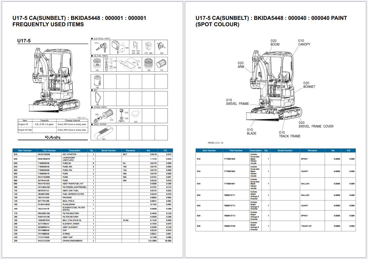
REALEASE :
REALEASE :
-
Kubota EPC KE FR 10.2021 Spare Parts Catalog Program
Price range: 70 through 150 USDSize: 8.7GB (WinRAR Files)Type of Vehicle: Kubota tractors, Kubota Construction Machinery, Kubota Power Products, Kubota Utility VehicleType of program: Spare Parts CatalogDatabase + Interface Languages: English, French (KE FR)OS: Windows 7, Windows 8, Windows 10 32 & 64-bit (Tested on Windows 10 Pro 22h2 64bit)Date update: 10.2021Instruction: How To InstallHot
REALEASE :
11.05.2022
REALEASE :
11.05.2022
-
Kubota Dumper KC100HD Workshop Manual RY921-20110
20 USDSize: 2.72 MBFormat: PDFLanguage: EnglishBrand: KubotaType of Machine: DumperType of Manual: Workshop Manual, Wiring DiagramModel: Kubota KC100HD DumperPart Number: RY921-20110Publication Date: 2010Number of Pages: 48 Pages
REALEASE :
REALEASE :
-
Kubota Dumper KC70 Workshop Manual RY921-20110
20 USDSize: 2.85 MBFormat: PDFLanguage: EnglishBrand: KubotaType of Machine: DumperType of Manual: Workshop Manual, Wiring DiagramModel: Kubota KC70 DumperPart Number: RY921-20110Publication Date: 2009Number of Pages: 40 Pages
REALEASE :
REALEASE :
-
Kubota Gasoline Diesel Engine Collection Workshop Service Manual Information PDF DVD
Original price was: 500.240Current price is: 240. USDKubota Gasoline & Diesel Engine 4.27GB Collection Workshop Service Manual PDF DVDSize: 4.27 GB (PDF Files)Language: ENFormat: PDFBrand: KubotaTypes of Vehicle: Gasoline & Diesel EngineTypes of Manuals: Workshop Service ManualQuantity of CD: 1 DVDOS: All WindowsHigh-Speed link DownloadHot-52%
REALEASE :
01.07.2022
REALEASE :
01.07.2022
-
Kubota Dumper KC250H KC250HR Workshop Manual 97899-61750
20 USDSize: 2.79 MBFormat: PDFLanguage: EnglishBrand: KubotaType of Machine: DumperType of Manual: Workshop Manual, Electric and Hydraulic DiagramModel: Kubota KC250H KC250HR DumperPart Number: 97899-61750Publication Date: 2008Number of Pages: 58 Pages
REALEASE :
REALEASE :
-
Kubota Excavator KX057-4 U55-4 Tier 4 Operators Manual RD358-8131-6 2009
10 USDSize: 7.46 MBFormat: PDFLanguage: EnglishBrand: KubotaType of Machine: ExcavatorType of Manual: Operators ManualModel: Kubota KX057-4 U55-4 Tier 4 ExcavatorEngine: V2607-DI-E3-BH-5, V2607-DI-E3-BH-3Part Number: RD358-8131-6Publication Date: 2009Number of Pages: 127 Pages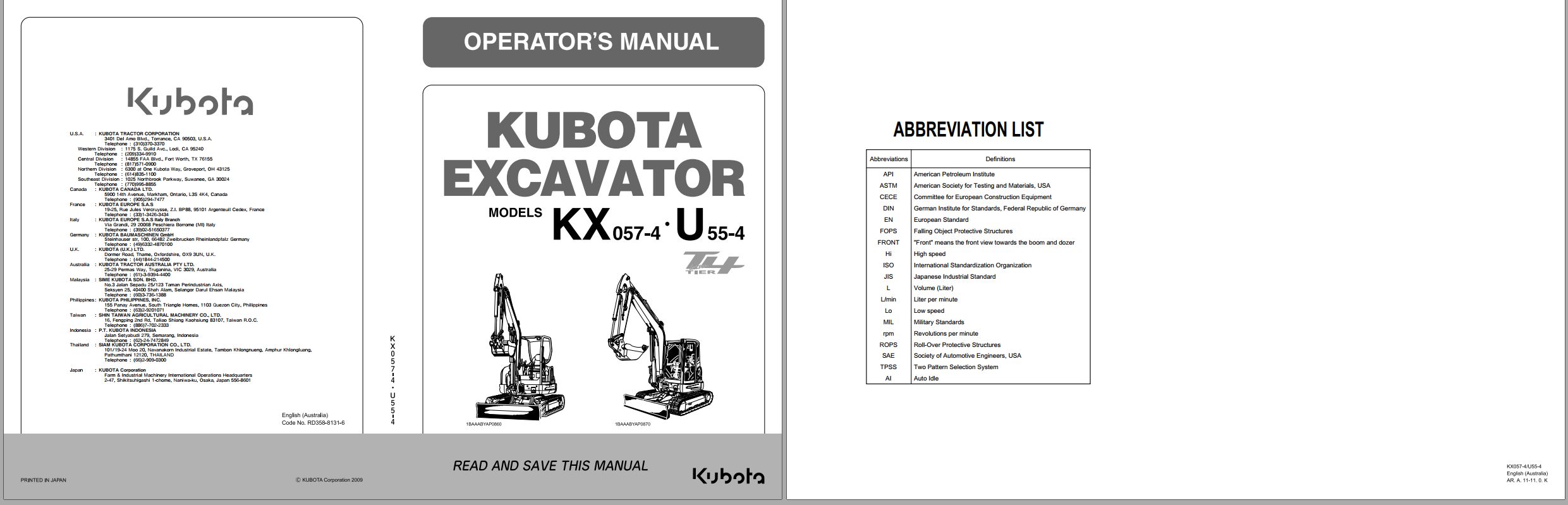
REALEASE :
REALEASE :
-
Kubota Excavator U15 U15-3 Workshop Manual 97899-61482
40 USDSize: 145.83 MBFormat: PDFLanguage: EnglishBrand: KubotaType of Machine: ExcavatorType of Manual: Workshop Manual, Electric and Hydraulic DiagramsModel: Kubota U15 U15-3 ExcavatorPart Number: 97899-61482Number of Pages: 766 Pages
REALEASE :
REALEASE :