
1 ITEMVIEW CART

Total: 160.00
Expert Support
Full Speed
100% Working
20 USD
Contents:
Wsm_Kx-121-3_161-3
Contents
I. General
A. Body And Engine Identification Marks
B. Safety Precautions For Servicing, Disassembly And Reassembly
A. Safety Measures Before Starting Work
B. Safety Measures During Work
C. Preparation For Disassembly
D. Precautions For Disassembly And Reassembly
C. Important Safety Process And Critical Functional Process
A. Essential Adhesives
B. Important Safety Process .
C. Important Critical Functional Process .
D. Important Inspection Items After Reassembling
A Operate The Machine And Check For Unusual Noise And Vibrations.
B Make Sure The Safety Decals And Wire Harness Clamps Are In Their Specified Positions.
C With The Machine Front In A Specified Posture, Check The Amount Of Hydrauric Oil
E. Servicing Fundamentals
A. Items For Servicing
B. O-Ring, Oil Seal, Circlip And Roll Pin
C. Piping
F. Maintenance Intervals
A. KTC, KCL, KTA-Version
B. Eu-Version
C. Hydraulic Oil Check For Machines With Hydraulic Breakers
G. Water And Oil Quantity
H. Recommended Oil
I. Filters
J. Compatibility Table Of Main Components Between U45-3. And Kx121-3, 161-3
Ii. Machine Body(Mechanism Section)
A. Product Feature
A. A New Load Sensing System.
B. Low Operating Cost, Easy To Service
C. Built For Tough Work, Not Tough On The Operator.
B. Standard Equipment
C. Machine Specifications
A. Kx121-3 Eu-Version
B. Kx161-3 Eu-Version
C. Kx121-3 KTC, KCL, KTA-Version
D. Component Interchangeability
A. Bucket Interchangeability
B. Arm
E. Machine Structure
A. Front Attachment : Kx121-3, Eu-Version
B. Seat & Control Box
C. Control Linkage
D. Engine Mount : Kx161-3
E. Undercarriage : Kx121-3
F. Rubber Track
G. Iron Track
H. Track Conversion : Kx121-3
Ii. Machine Body(Service Section)
A. Specifications
A. Machine Weight
B. Machine Specifications
C. Lever Stroke And Operating Force
D. Dimensions Of Parts
B. Front Attachment
A. Parts Designation
B. Exchange Of Bucket (Kubota Japan Bucket)
C. Exchange Of Bucket Teeth And Side Cutter
D. Installing Direction Of Dust Seal
E. Installation Of Thrust Collar On The Swing Bracket
F. Installing Pin, Bush And Shim (1):Kx121-3, Kx161-3
G. Installing Pin, Bush And Shim (2):Kx121-3, Kx161-3
H. Installing Pin, Bush And Shim Of Bucket:Kx121-3, Kx161-3
I. Installing Local Bucket : Kx121-3, Kx161-3
J. Greasing Points
K. Front Hoses And Clamps : Kx121-3, Kx161-3
F’. Installing Pin, Bush And Shim (1):Kx161-3 KTC, KCL, KTA
G’. Installing Pin, Bush And Shim (2):Kx161-3, KTC, KCL, KTA
H’. Installing Pin, Bush And Shim Of Bucket:Kx161-3, KTC, KCL, KTA
L. Installing Direction Of Fixing Pin Bolts : Kx121-3
C. Upper Structure
A. Swivel Bearing
B. Pilot Control Lever : Kx121-3, Kx161-3
C. Traveling Lever : Kx121-3, Kx161-3
D. Traveling Lever Adjustment : Kx121-3, Kx161-3
E. Traveling Lever Lock : Kx121-3, Kx161-3
F. Accelerator Lever : Kx121-3, Kx161-3
G. Dozer Lever : Kx121-3, Kx161-3
H. Tpss Lever : KTC, KCL, KTA-Version : Kx121-3
I. Swing & Sp Pedal : Kx121-3, Kx161-3
J. Control Valve Links : Kx121-3, Kx161-3
K. Limit Switch Installation : Kx121-3, Kx161-3
L. Control Stand
M. Control Stand : Kx121-3
N. Installing Weight : Kx121-3, Kx161-3
O. Installing Covers : Kx121-3, Kx161-3
D. Cab Installation : KTC, KCL, KTA-Version
A. Mounting Bolt
B. Seal Rubber
C. Wiper : KTC, KCL, KTA-Version
D. Heater Hose : KTC, KCL, KTA-Version
E. Wire Harness : KTC, KCL, KTA-Version
F. Cab Glass Replacement Procedure
G. Defroster Hose : KTC, KCL, KTA
H. Defroster Hose : Eu
E. Under Carriage
A. Track Tension Device : Kx121-3, 161-3
B. Track Sag Distance
C. Crawler Installation
D. Track Roller And Upper Roller Installation
Iii. Engine
A. Specifications & Features
A. Technical Data : Kx121-3, Kx161-3
B. Performance Curve
C. Features
D. Structure And Function
B. Engine Mounting Procedure : Kx121-3
A. Engine Mount
B. Air Cleaner : Kx121-3, Kx161-3
C. Radiator : Kx121-3, Kx161-3
D. Muffler : Kx121-3, Kx161-3
E. Pump Coupling
F. Fuel Tank Installation : Kx121-3, Kx161-3
G. Fuel Tank Cushion : Kx121-3, Kx161-3
H. Fuel Hoses : Kx121-3, Kx161-3
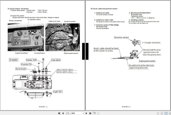
I. Accel Cable And Meter Cable
C. 03-M Series Engine Wsm
Iv. Hydraulic System(Mechanism Section)
A. Features Of Hydraulic System
Eee Hydraulic Systtem
(1)Three Big Features
(2) New Hydraulic System Features
(3) Component Of New Hydraulic System
(4) Circuit Comparison Between New Hydraulic System And Conventional Systems
(5) Feature 1. High Efficiency
(6) Feature 2. Easy Operation
(7) Feature 3. Economy
B. Hydraulic System Specifications
C. Main Pump
A. Structure & Performance Curve
B. Operating Principle
D. Control Valve
A. Specifications
B. General View Of Control Valve
C. Control Valve Circuit Diagram
D. Operating Principle
E. Automatic Air Bleeding In Hydraulic Pilot Section
F. Relief Valve/Anti-Cavitation Valve
E. Pilot Valve
A. Structure & Specifications
B. Pilot Valve Control Diagram
F. Swivel Motor
A. Structure & Specifications
B. Function Of Negative Brake
C. Function Of Valve Section
G. Rotary Joint (Swivel Joint)
H. Travel Motor
A. Structure & Specification
B. Operation Of Piston Motor
C. Function Of Anti-Cavitation Valve
I. Hydraulic Circuit Diagram
A. Kx121-3 European – Version
B. Kx161-3 European – Version
C. Kx121-3 KTC, KCL, KTA – Version
D. Hydraulic Components Layout
E. Kx161-3 European-Version
F. Kx161-3 KTC, KCL, KTA-Version
Iv. Hydraulic System(Service Section)
A. Troubleshooting
A. Case – Study : Abnormal Speed
B. Case – Study : The Power Is Weak.
C. Case – Study : Poor Manipulation And Abnormal Operation
C. Case – Study : Poor Manipulation And Abnormal Operation
D. Ls Control System Troubleshooting
E. Pump Component Trouble Causes And Remedy
F. Control Valve Component Troubleshooting
G. Travel Motor Component Troubleshooting
B.Specifications
A. Relief Valve Pressure Setting
B. Pump
C. Load Sensing Control System Data
D. Cylinder
E. Swivel Performance
F. Traveling Performance
C.Testing
A. Testing Instruments & Special Tools
B. Precautions In Handling The Pump
C. Pilot Pressure
D. Main Relief Valve
E. Unload Valve
F. Overload Relief Valve
G. Swivel Brake Valve Pressure
H. Measuring The Main Pump Max. Flow Rate
I. Measuring The Main Pump’s Stand-By Flow Rate
J. Ls Control Pressure
K. Traveling Motor Drain Amount
L. Swivel Motor Drain Amount
M.Swivel Motor Block Performance
N. Traveling Motor Block Performance
O. Operating Speed
P. Straight Travel Performance
Q. Cylinder Natural Fall Amount
R. Control And Traveling Lever Operating Force
S. Lever Stroke
D. Disassembling And Assembling
A. Coupling Flange
B. Pump:Kx121-3, Kx161-3
C. Control Valve
D. Pilot Valve
E. Swivel Motor
F. Wheel Motor : Kx121-3, 161-3
G. Rotary Joint : Kx121-3, 161-3
H. Cylinder (KE, KDG, Kuk Version)
H. Cylinder (KTC, KCL, KTA Version)
I. Other Hydraulic Device
J. Hoses
V. Electrical System(Mechanism Section)
A. Components, Harness Layout & Coupler
A. Components, Harness Layout & Coupler : Kx161-3 Ai-Version
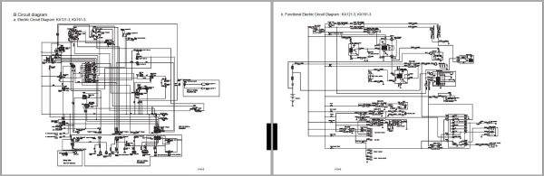
B. Circuit Diagram
A. Electric Circuit Diagram: Kx121-3, Kx161-3
B. Functional Electric Circuit Diagram : Kx121-3, Kx161-3
C. Cab Electric Diagram : Kx121-3, Kx161-3
D. Cab Electric Diagram : Kx121-3
E. Electric Circuit Diagram : Kx161-3 Ai-Version
F. Electric Wiring Diagram : Kx161-3 Ai-Version
C. Function Of Main Circuit
A. Battery Circuit (Non-Ai-Version)
B. Safety Relay Circuit (Automatic Release Function) Non-Ai-Version
C. Auto Glow Circuit (Non-Ai-Version)
D. Fuel Control Circuit (Non-Ai, Ai-Version)
E. Engine Oil Pressure Sensor Circuit (Non-Ai, Ai-Version)
F. Horn Circuit (Non-Ai, Ai-Version)
G. Cab & Working Lamp Circuit (Non-Ai, Ai-Version)
H. Meter Panel (Non-Ai-Version)
I. Heater Circuit (Non-Ai, Ai-Version)
J. Travel Hi-Speed Control Circuit (Non-Ai, Ai-Version)
K. Auto Idle Control System (Ai-Version)
L. Battery Direct Line (Ai-Version)
M. Starter Lock Relay & Auto Release Relay (Ai-Version)
N. Self Holding Relay Circuit (Ai-Version)
O. Water Temp. Sensor Circuit (Ai-Version)
P. Meter Panel (Ai-Version)
Q. Ai Controller Unit (Ai-Version)
D. Structure And Function Of Main Components
A. Key Switch (Engine Starter Switch)
B. Water Temp. Sensor & Gauge
C. Fuel Gauge
D. Safety Lever Lock Switch, Travel Hi-Low Pedal Switch
E. Relay
F. Engine Speed Sensor
G. Governor Sensor
H. Accel Sensor (Electric Accelerator)
I. Ai Pressure Switch
J. Accelerator
K. Measurement
L. Introduction Of Semiconductor
M. Introduction Of Magnetism
N. Introduction Of Starter Motor
O. Introduction Of Generator, Alternator
V. Electrical System(Service Section)
A. Wire Harness Installation
A. Precautions
B. Engine Earth, Starter Switch
C. Main Harness
D. Control Box
E. Engine Harness
F. Front Harness
G. Ai Motor Installation : Ai-Version
H. Control Box : Ai-Version
I. Main Harness : Ai-Version
B. Troubleshooting
A. General
B. Troubleshooting Flow Chart
C. Front Attachment
D. Engine Electrical System
E. Auto Idle System
F. Ai Version: Ai Controller (Built-In Microcomputer) Cases Of Trouble Diagnosis With Circuit Tester
G. Cases Of Trouble Diagnosis With Circuit Tester
H. Auto Idle(Ai) Version: Trouble Diagnosis With Lamp
C. Electrical Equipment Specifications
Vi. Optional Unit : Air Conditioner(Mechanism Section)
A. Air Condition System
A. Introduction Of Air Conditioner
B. Components And Location
C. A/C System, Electric Circuit Diagram
B. Function And Structure
A. Compressor
B. High Pressure Relief Valve
C. Magnetic Clutch
D. Condenser
E. Receiver
F. Dual Pressure Switch
G. Air Conditioner Unit
H. Refrigerant
C. Electrical System
A. Electrical Circuit
C. Air Conditioner Blower Switch
D. Dual Pressure Switch
E. Thermostat
F. Control Panel
G. Air Flow
D. Technical Terms
A. Heat
B. Temperature
C. Humidity
D. Pressure
E. Change Of State
F. What Is A Heater?
G. Principle Of Cooling
H. Principle Of Air Conditioning
I Refrigeration Cycle
J. Practical Control Of Air Conditioner
K. Moller Diagram
L. Basic Operation Of Cooling Cycle
M. Calculation Of Refrigeration Capacity And Power From Moller Diagram
N. Calculation Of Flow Of Circulating Refrigerant
O. Theoretical Performance (Sample Calculation)
Vi. Optional Unit : Air Conditioner(Service Section)
A. Troubleshooting
A. Visual And Audible Inspection
B. Components
C. Diagnosis Flow Chart
D. Troubleshooting From Problem Symptoms (Except Refrigeration Cycle Troubles)
B. Servicing Specifications
A. Specifications Of A/C System And Components
B. Performance Specifications
C. Adjustment And Testing
D. Ambient Temperature Vs Normal High-Low Pressure Range
E. Tightening Torques
C.Regular Check And Service Points
A. Maintenance Interval ; Air Conditioner
B. Regular Service Points
D. Precautions At Repairing Refrigerant Cycle
E. Precaution For Installation And Maintenance
F. Checking And Charging Refrigerant Cycle
A. Handling Of Service Tools
B. Checking With Manifold Gauge
C. Discharging, Evacuating And Charging
G. Main Components Servicing
A. Compressor
B. Condenser And Receiver
C. Air Conditioner Unit
D. Electrical System Components
E. Heater Hose And Control Cable
F. Cooler Hoses Installation
G. Duct Cover Installation
H. Noise Absorber And Trims
I. Labels
J. Wire Harness Route
K. Wire Harness Clamps For A/C Version
L. Parts Identification Of Air Conditioner Version
Vii. Optional Unit (KTC) : Angle Dozer (Kx121-3)
A. Specifications
B. Machine Quality Specifications
C. Lubrication Point Of Angle Dozer
D. Dozer Lever
A. Dozer Angle Operation
B. Dozer Lever, Angle
E. Control Valve
A. Specifications
B. General View Of Control Valve
C. Control Valve Circuit Diagram
D. Angle Section
E. Adaptor Installation
F. Rotary Joint
A. Assembling Of The Rotary Joint
B. Adaptor Installation
C. Hose Connection
G. Under Carriage
A. Angle Dozer
H. Hydraulic Circuit
A. Kx121-3 Hydraulic Circuit (USA, Angle Blade)
REALEASE :
REALEASE :
REALEASE :
REALEASE :
REALEASE :
REALEASE :

REALEASE :
REALEASE :

REALEASE :
REALEASE :

REALEASE :
01.07.2022
REALEASE :
01.07.2022
REALEASE :
REALEASE :

REALEASE :
11.05.2022
REALEASE :
11.05.2022
 Automotive - Heavy Equipment - Truck & Bus - Forklift - Crane