
0 ITEMSVIEW CART

✓
Expert Support
✓
Full Speed
✓
100% Working
Kubota Reformer System V1505-T-E4 Diagnostic Manual 9Y110-04120
Size: 13.07 MB
Format: PDF
Language: English
Brand: Kubota
Type of Machine: Reformer System
Type of Manual: Diagnostic Manual
Model: Kubota V1505-T-E4 Reformer System
Part Number: 9Y110-04120
Number of Pages: 233 Pages
10 USD
- Description
Description
Contents:
V1505-T-E4(For Zero Turn Mower)
I Information
1 Reformer System
Mechanism
1. Basic System Information
[2] Fuel System
[3] Intake And Exhaust System
[4] Available Data Monitor Signals (Level 1)
(1) Monitor Items
(2) Normal Value
[5] Ecu Terminal Layout
2. Wiring Diagram
[1] Zd1511
Servicing
1. General
[1] Overall Diagnostic Procedure
[2] Questioning
[3] List Of Malfunction Symptom
[4] Actions For Non-Reoccurring Malfunctions
2. Diagnostic Tool Connection Procedure
[1] Diagnostic Connector Positions
[2] Diagnostic Tool Connection Procedure
[3] Checking The Communication Operation Of The Interface (Dst-I)
[4] Checking The Operation Of The Ecu
(1) Starting Diagmaster
(2) Dst-I Communication Settings
3. Active Test And Utility
[1] Active Test
(1) Glow Relay On-Off Function
(2) Egv Fuel Feed Pump On-Off Function
(3) Air Valve 1 For Fuel Reformer Operate Function
(4) Air Valve 2 For Fuel Reformer Operate Function
(5) Air Blower For Fuel Reformer On-Off Function
(6) Fuel Pump For Fuel Reformer Operate Function
(7) Catalyst Heater For Fuel Reformer On-Off Function
(8) Regen. Gas Glow For Fuel Reformer On-Off Function
(9) Purge Function For Catalyst Of Fuel Reformer
[2] Utility
(1) Gear Case Or Gear Case Gasket Or Rack Position Sensor Exchange
(2) Rack Position Sensor Correction
4. Replace Ecu
5. Diagnosis By Malfunction Symptom
[1] List Of Malfunction Causes By Symptom
[2] Diagnosis By Malfunction Symptom
(1) Engine Warning Light Comes On
(2) Engine Does Not Start
(3) Takes A Long Time Before Engine Starts
(4) Idle Failure
(5) Engine Noise
(6) High Fuel Consumption
(7) Poor Acceleration (Insufficient Output)
(8) Abnormal Black Smoke Emitted
(9) Abnormal White Smoke Emitted
(10)Engine Stalls On Deceleration
6. Diagnostic Procedure By Dtc
[1] Dtc List
[2] Diagnostic Procedure By Dtc
(1) Coolant Temperature Sensor Abnormality (Dtc P0117 – 110-4, P0118 – 110-3)
(2) Engine Overheat (Dtc P0217 – 110-0)
(3) Engine Overrun (Dtc P0219 – 190-0)
(4) Engine Speed Sensor Abnormality (Dtc P0335 – 636-8)
(5) Exhaust Gas Temperature Sensor 1 (T1) Abnormality (Dtc P0543 – 3242-4,
P0544 – 3242-3)
(6) Exhaust Gas Temperature Sensor 0 (T0) Abnormality (Dtc P0546 – 4765-4,
P0547 – 4765-3)
(7) Battery Voltage Abnormality (Dtc P0562 – 168-4, P0563 – 168-3)
(8) Ecu Flash-Rom And Cpu Abnormality (Dtc P0605 – 628-2, P0606 – 1077-2,
P0606- 523527-2)
(9) Sensor Supply Voltage 1 Abnormality (Dtc P0642 – 3509-4)
(10)Circuit Of Burner Glow Abnormality (Dtc P1801 – 523766-6, P1802 – 523766-5)
(11)Circuit Of Fuel Pump For Fuel Reformer Abnormality (Dtc P1803 – 523767-5, P1804
– 523767-4, P1805 – 523767-3)
(12)Blower Motor Malfunction (Dtc P1806 – 523768-5, P1807 – 523768-5)
(13)Circuit Of Solenoid Valve 1 For Fuel Reformer Abnormality (Dtc P1808 – 523770-5,
P1809 – 523770-4, P1810 – 523770-3)
(14)Circuit Of Solenoid Valve 2 For Fuel Reformer Abnormality (Dtc P1811 – 523769-5,
P1812 – 523769-4, P1813 – 523769-3)
(15)Burner Temperature Sensor Abnormality (Dtc P1815 – 523762-3, P1816 –
523762-4)
(16)Blower Pressure Sensor Abnormality (Dtc P1818 – 523764-3, P1819 – 523764-4)
(17)Rack Position Sensor Abnormality (Dtc P1827 – 523773-3, P1828 – 523773-4)
(18)Electric Governor Solenoid Circuit Abnormality (Dtc P1830 – 523771-5, P1831 –
523771-6)
(19)Reformer Temperature Sensor Abnormality (Dtc P1832 – 523763-3, P1833 –
523763-4)
(20)Reformer Temperature Abnormality (Dtc P1834 – 523753-0
(21)Blower Pressure Abnormal (Dtc P1835 – 523751-0)
(22)Circuit Of Glow Relay For Fuel Reforming Abnormality (Dtc P1836 – 523765-3, P1837
– 523765-4)
(23)Buzzer Circuit Abnormality (Dtc P1838 – 523759-4, P1839 – 523759-3)
(24)Feed Pump Circuit Abnormality (Dtc P1840 – 523761-3, P1841 – 523761-4)
(25)Reformer Abnormal (Dtc P1844 – 523755-2)
(26)Fail To Rise Dpf Temperature (Dtc P1845 – 523756-2)
(27)Over Current In Circuit Of Blower Motor (Dtc P1846 – 523768-6)
(28)Fail To Ignite Burner (Dtc P1848 – 523757-2)
(29)Low Coolant Temp. For Dpf Regeneration (Dtc P1849 – 523750-2)
(30)Eep Write Error (Dtc P1850 – 523749-2)
(31)Excessive Power Consumption During Regeneration (Dtc P1851 – 523748-2)
(32)High Frequency Of The Interruption Of Automatic Regeneration (Dtc P1856 –
523742-2)
(33)Eeprom Check Sum Error (Dtc P1990 – 523700-13)
(34)Accelerator Position Sensor 1 Abnormality (Dtc P2122 – 91-4, P2123 – 91-3)
(35)Accelerator Position Sensor 2 Abnormality (Dtc P2127 – 29-4, P2128 – 29-3)
(36)Barometric Pressure Sensor Error (Dtc P2228 – 108-4, P2229 – 108-3)
(37)Exhaust Gas Temperature Sensor 2 (T2) Abnormality (Dtc P242c – 3246-4,
P242d – 3246-3)
(38)Differential Pressure Sensor 1 Abnormality (Dtc P2454 – 3251-4, P2455 – 3251-3)
(39)Exhaust Gas Temperature Sensor 0: Emergency High (Dtc P3002 – 4765-0)
(40)Exhaust Gas Temperature Sensor 1: Emergency High (Dtc P3003 – 3242-0)
(41)Exhaust Gas Temperature Sensor 2: Emergency High (Dtc P3004 – 3246-0)
(42)Excessive Pm3 (Dtc P3006 – 3701-15)
(43)Excessive Pm4 (Dtc P3007 – 3701-16)
(44)Excessive Pm5 (Dtc P3008 – 3701-0)
(45)Parked Regeneration Time Out (Dtc P3013 – 523590-16)
(46)All Exhaust Gas Temperature Sensor Failure (Dtc P3018 – 523599-0)
(47)High Exhaust Gas Temperature After Emergency High Temperature Dtc (Dtc
P3023 – 523601-0)
(48)High Frequency Of Regeneration (Dtc P3024 – 523602-0)
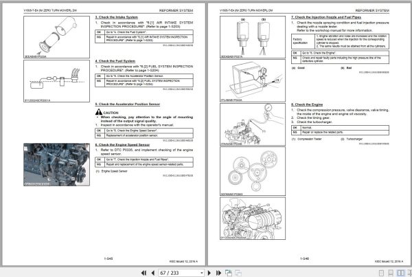
7. Inspection Procedure For Each System
[1] Air Intake System Inspection Procedure
[2] Fuel System Inspection Procedure
[3] Electric System Inspection Procedure
(1) Basics Of Checking Electrical – Electronic Circuit Systems
Related Products
-
Kubota Agricultural Spare Parts Catalog 17.4 GB PDF
Original price was: 300.210Current price is: 210. USDThis is an offline spare parts catalog, you need to use this to sell the spare parts and it can help you a little with assembly. It’s from a manufacturer and the best in the world.Hot-30%
REALEASE :
REALEASE :
-
Kubota Construction, Tractor Engine Workshop Services Operator Parts Information DVD
Original price was: 200.100Current price is: 100. USDKubota Construction, Tractor & Engine Workshop Services Operator & Parts Manual DVDSize: 4.12 GB (Unpack)Language: EnglishFormat: PDF & HTMLBrand: KubotaType of Machine: Kubota Construction, Tractor & EngineWindows: All Windows 32 & 64bitOffline VersionDVD: 1 ISOHigh Speed Link downloadHot-50%
REALEASE :
14.06.2022
REALEASE :
14.06.2022
-
Kubota Zero Turn Mower ZD326-EU Spare Parts Catalog EN PT
30 USDFormat: PDFSize: 120.58 MBLanguage: English, PortugueseBrand: KubotaType of Machine: Zero Turn MowerType of Manual: Spare Parts CatalogModel: Kubota ZD326-EU Zero Turn MowerNumber of Pages: 176 Pages
REALEASE :
REALEASE :
-
Kubota Construction, Tractor & Engine Operators Manual DVD
Original price was: 70.45Current price is: 45. USDKubota Construction, Tractor & Engine Operators Manual DVDSize: 0.99 GBFormat: PDFBrand: KubotaType of Machine: Kubota Construction, Tractor & EngineType of document: Operator’s Manual, Operating Instructions for Kubota.Windows: All Windows 32 & 64bit, MACHigh-Speed Link download Details Content: KUBOTA EngineKUBOTA ExcavatorsKUBOTA GeneratorsKUBOTA MowersKUBOTA Specialist Turf EquipmentKUBOTA Track LoadersKUBOTA TractorsKUBOTA Utility VehiclesKUBOTA Wheel LoadersHot-36%
REALEASE :
28.06.2022
REALEASE :
28.06.2022
-
Kubota Zero Turn Mower ZD326-EU-2 Spare Parts Catalog EN PT
30 USDFormat: PDFSize: 112.79 MBLanguage: English, PortugueseBrand: KubotaType of Machine: Zero Turn MowerType of Manual: Spare Parts CatalogModel: Kubota ZD326-EU-2 Zero Turn MowerNumber of Pages: 124 Pages
REALEASE :
REALEASE :
-
Kubota Agricultural Equipment Collection Diagnosic Workshop Service Information PDF DVD
Original price was: 1,500.340Current price is: 340. USDKubota Agricultural Equipment 46.7GB Collection Diagnosic Workshop Service Manual PDF DVDSize: 46.7 GB (PDF Files)Language: EN, DE (Only two files have the DE language, You can see the content below)Format: PDFBrand: KubotaTypes of Vehicle: AgriculturalTypes of Manuals: Diagnosic Manual, Workshop Service ManualQuantity of CD: 1 DVDOS: All WindowsHigh-Speed link DownloadHot-77%
REALEASE :
29.06.2022
REALEASE :
29.06.2022
-
Kubota Agricultural Implements Collection Spare Parts Catalog PDF DVD
Original price was: 300.150Current price is: 150. USDKubota Agricultural Implements 2.11GB Collection Spare Parts Catalog PDF DVDSize: 2.11 GB (PDF Files)Language: EN, DE (Only one file has the DE language, You can see the content below)Format: PDFBrand: KubotaTypes of Vehicle: Agricultural ImplementsTypes of Manuals: Spare Parts CatalogQuantity of CD: 1 DVDOS: All WindowsHigh-Speed link DownloadHot-50%
REALEASE :
04.07.2022
REALEASE :
04.07.2022
-
All Kubota Takeuchi Dieci Manitou Merlo Bobcat CNH Hyster Yale Diagmaster 2026 Diagnostic Program Combo
Price range: 380 through 1,300 USDThe combo included:Size: You need to prepare 50GB of free space on disk C for the best installationRecommend OS: Windows 10, 11 64 bit (Tested on Windows 10 pro 22h2 64bit english version)Hot
REALEASE :
REALEASE :