
1 ITEMVIEW CART

Total: 180.00

Expert Support
Full Speed
100% Working
150 USD
Contents:
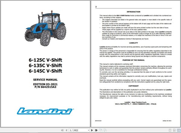
– Cover Page
– Introduction
– Liability
– Purpose Of The Manual
– Copyright
– Table Of Contents
– 1001 – Safety
General Instructions
Symbols
Danger Signs
Tightening Torques
– 2 – Engine
Technical Specifications
Annexes
– 3005 – Tanks And Reservoirs
Technical Specifications
Safety
Procedures
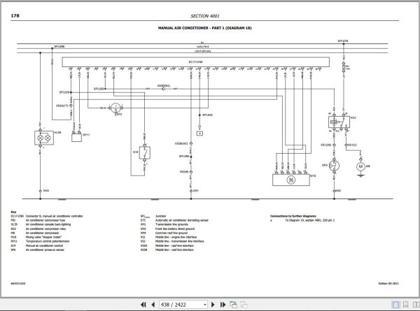
– 4001 – Descriptions – Wiring Diagrams – Connectors
Technical Specifications
Safety
Symbols And Names
Fuses And Relays
Controls
Sockets
Light Units
Dsm Monitor
Topographic Diagrams
Descriptions And Diagrams
Complete List Of Connections
– 4002 – Instrument Cluster Setup
General Instrument Cluster Specifications
– 5 – Steering System Operation
Description
– 5001 – Steering Column And Power Steering System
Technical Specifications
Safety
Procedures
– 5002 – Power Steering System
Technical Specifications
Procedures
– 6 – Transmission – Torsional Coupling
Transmission
Torsional Coupling
Cvt System
– 6001 – Engine – Transmission Coupling
Sections And Perspective Views
Torsional Coupling
– 6006 – Synchronised Gearbox And Ranges
Technical Specifications
Sections And Perspective Views
Safety
Splitting The Engine Cvt Gearbox Assembly Housing
Transmission Disassembly
Re-Assembling And Shimming Of The Speed Sequencer Intermediate Shaft
Re-Assembly And Adjustment Of The Speed Sequencer Actuator
– 6012 – Rear Differential
Technical Specifications
Sections And Perspective Views
Safety
Procedures
– 6018 – Side Final Drives
Technical Specifications
Sections And Perspective Views
Safety
Procedures
– 6019 – Rear Power Take-Off
Technical Specifications
Safety
Rear Power Take-Off
– 6021 – Front Axle
Technical Specifications
Safety
Differential Lock Assembly
Side Final Drives
Diagnosis Of Malfunctions In Locking Device Of Front Differential
– 6021 – Carraro Front Axle
Carraro Front Axle
Annexes
– 7 – Brakes (Operation)
Brake Circuits
Hydraulic Trailer Brake
Pneumatic Trailer Brakes
Iso And Functional Diagrams – Air Braking System
Troubleshooting
Diagnostic Tests Of The Air System
– 7003 – Brakes Overhaul And Adjustments
Safety
Parking Brake
– 8 – Hydraulic Components Operation
Technical Specifications
Hydraulic Circuit
Hydraulic Pumps
Hydrostatic Power Pack
Solenoid Valve Pack For Users Control
Solenoid Valves Pack, Speed Sequencer
Solenoid Valves Pack For Pto Control
Clutches Solenoid Valves Pack
Oil-Oil Heat Exchanger
Suspended Axle
Electronically Controlled Hydraulic Hitch
Auxiliary Control Valves
– 8001 – Troubleshooting Of The Hydraulic System
Technical Specifications
Troubleshooting
Hydraulic System Diagnostic Testing
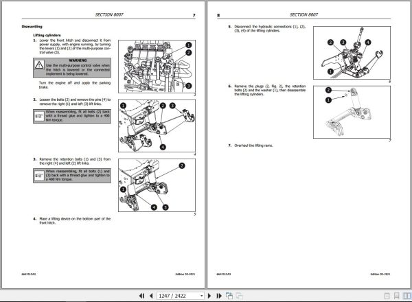
– 8007 – Front Hitch And Pto
Technical Specifications
Safety
Front Hitch
Front Pto
– 9005 – Operator Seat
Safety
Description
Annexes
– 10 – Controllers – Can Line Operation
Can Bus System
Safety
Error Handling Via Can
Check-Control And Troubleshooting
Descriptions And Diagrams
Basic Checks
– 10001 – Midmount Valves Controller Error Codes, Troubleshooting, Descriptions, Wiring Diagrams
Technical Specifications
Safety
General Information About The Midmount Valves Controller
Descriptions And Diagrams
Error Codes – Engine Controller Electrical Diagnosis 21
Error Codes – Settings And Programming
– 10002 – Hitch Controller Calibration, Error Codes,Troubleshooting, Descriptions, Wiring Diagrams
Technical Specifications
Safety
General Information
Rear Hitch Calibration
Descriptions And Diagrams
Error Codes – Electrical Diagnosis
Error Codes – Hitch Controller Settings And Programming
– 10003 – Suspended Axle Controller Calibration, Error Codes, Troubleshooting, Descriptions, Wiring Diagrams
Technical Specifications
Safety
General Information About The Suspended Axle Controller
Suspended Axle Calibration
Descriptions And Diagrams
Error Codes – Electrical Diagnosis
Faults
– 10005 – Engine Controller Error Codes, Troubleshooting, Descriptions, Wiring Diagrams
Technical Specifications
Safety
General Information About The Engine Controller
Descriptions And Diagrams
Basic Checks
Error Codes – Electrical Diagnosis Engine Controller
Error Codes – Electrical Diagnosis Ats Controller
Error Codes – Settings And Programming
– 10006 – Transmission Controller Calibration, Error Codes, Troubleshooting, Descriptions, Wiring Diagrams
Technical Specifications
Safety
General Information About The Transmission Controller
Operating Temperature
Transmission Calibration
Descriptions And Diagrams
Diagnostic Trouble Codes
– 10007 – Armrest Interconnection Diagram Description And Wiring Diagrams
Technical Specifications
Safety
General Information On The Armrest Interconnection Board
Multipurpose Armrest
Descriptions And Diagrams
– 10008 – A/C Controller Error Codes, Troubleshooting, Descriptions, Wiring Diagrams
Technical Specifications
Safety
General Information About The A/C Controller
Descriptions And Diagrams
Error Codes – Electrical Diagnosis
Error Codes – Settings And Programming
– 10009 – Instrument Cluster Controller Calibration, Error Codes, Troubleshooting, Descriptions, Wiring Diagrams
Technical Specifications
Safety
General Information About The Instrument Cluster Controller
Calibration Of Wheel Radius Index
Descriptions And Diagrams
Error Codes – Electrical Diagnosis
Error Codes – Settings And Programming
– 10010 – Controller Programming Diag4 Argo Tractors
Technical Specifications
Description
– 10012 – Controller Of Can/Iso Interface Description And Wiring Diagrams
General Information About The Can/Iso Interface Controller 11786
Descriptions And Diagrams
– 10013 – Isobus Controller Error Codes, Troubleshooting, Descriptions, Wiring Diagrams
Technical Specifications
Safety
General Information On The Isobus System
Error Codes Isobus Tecu Controller
Descriptions And Diagrams
– 10014 – Trailer Brake System Controller Calibration, Error Codes, Troubleshooting, Descriptions, Wiring Diagrams
Technical Specifications
Safety
General Information About The Trailer Brake Controller
Descriptions And Diagrams
Error Codes – Trailer Brake System Controller, Electrical Diagnosis
Error Codes – Settings And Programming

REALEASE :
REALEASE :

REALEASE :
REALEASE :
REALEASE :
REALEASE :
REALEASE :
REALEASE :
REALEASE :
REALEASE :

REALEASE :
REALEASE :

REALEASE :
REALEASE :

REALEASE :
REALEASE :
Automotive - Heavy Equipment - Truck & Bus - Forklift - Crane