
0 ITEMSVIEW CART

✓
Expert Support
✓
Full Speed
✓
100% Working
Landini Tractor 6-145 to 7-215 ROBO-SHIFT ACTIVE Service Manual 6622108A1 EN
Size: 672.80 MB
Format: PDF
Language: English
Brand: Landini
Type of Machine: Tractor
Type of Manual: Service Manual, Hydraulic and Electrical Diagrams
Model: Landini Tractor ACTIVE
6 Series: 6-145 ROBO-SHIFT, 6-160 ROBO-SHIFT, 6-175 ROBO-SHIFT
7 Series: 7-160 ROBO-SHIFT, 7-175 ROBO-SHIFT, 7-215 ROBO-SHIFT
Part Number: 6622108A1
Publication Date: 2017
Number of Pages: 3320 Pages
100 USD
- Description
Description
Contents:
– Cover Page
– Introduction
– Liability
– Purpose Of The Manual
– Copyright
– Table Of Contents
– 1001
Safety
– 2
Engine
– 2002
Exhaust Gases Treatment System
– 3005
Tanks
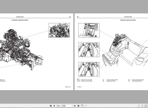
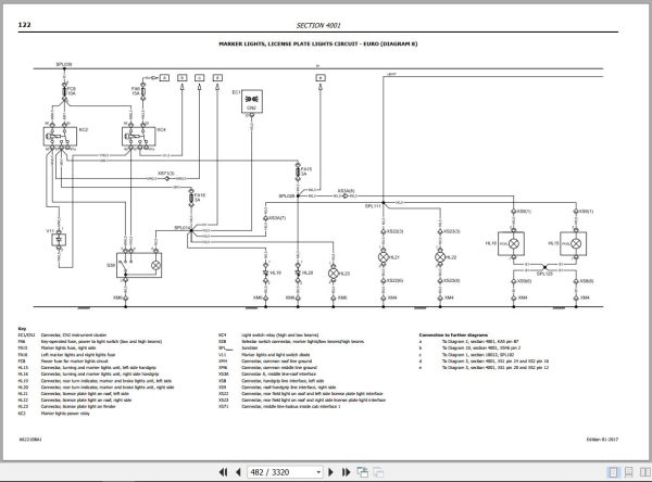
– 4001
Descriptions – Wiring Diagrams – Connectors
– 4002
Instrument Cluster Setup
– 5001
Steering Column And Power Steering System
– 5002 Std
Standard Power Steering
– 5002 Elet
Electronic Power Steering
– 6
Transmission – Torsional Coupling
– 7
Brakes Operation
– 8 Pist
Hydraulic Components Setup With Piston Pump Operation
– 8 Ingr
Hydraulic Components Setup With Gear Pump Operation
– 8001 Ingr
Troubleshooting Of The Hydraulic System – Gear Pump
– 8001 Pist
Troubleshooting Of The Hydraulic System – Piston Pump
– 8003
Piston Pump
– 8004
Gear Pump
– 8007
Front Hitch And Pto
– 9001
Adjustment Of Pedals, Levers And Switches
– 9005
Operator’s Seat
– 10
Controllers – Can Line Operation
– 10001
Midmount Valves Controller Description And Wiring Diagrams
– 10002
Hitch Controller And Auxiliary Control Valves Calibration, Error Codes, Troubleshooting, Descriptions, Wiring Diagrams
– 10003
Suspended Axle Controller Calibration, Error Codes, Troubleshooting, Descriptions, Wiring Diagrams
– 10005
Engine Controller Error Codes, Troubleshooting, Descriptions, Wiring Diagrams
– 10006 – Trasmission Controller
Technical Specifications
Safety
General Information About The Transmission Controller
Operation Modes – System Statuses
Transmission Calibration
Transcoding Table Of Error Codes
Error Codes – Electrical Diagnosis
Error Codes – Settings And Programming
Descriptions And Diagrams
– 10008
A/C Controller Error Codes, Troubleshooting, Descriptions, Wiring Diagrams
– 10009
Instrument Cluster Controller Calibration, Error Codes, Troubleshooting, Descriptions, Wiring Diagrams
– 10011
Cab And Suspended Axle Controller Calibration, Error Codes, Troubleshooting, Descriptions, Wiring Diagrams
– 10012
Controller Of Can/Iso Interface Description And Wiring Diagrams
– 10013
Isobus Controller And Satellite Guide System Error Codes, Troubleshooting, Descriptions, Wiring Diagrams
Related Products
-
Landini Tractor Trekker 4-105 To 4-110 FM CP04 Operators Manual 6621074A4 2021
20 USDSize: 32.41 MBFormat: PDFLanguage: EnglishBrand: LandiniType of Machine: TractorType of Manual: Operators ManualModel: Landini TractorTrekker 4-105 STD ; Trekker 4-115 STDTrekker 4-085 F/M ; Trekker 4-095 F/MTrekker 4-105 F/M ; Trekker 4-110 F/MEngine:Deutz C4DT69 Engine – Trekker 4-105 STDDeutz C4DT74 Engine – Trekker 4-115 STDDeutz 2.9 TCD L4 Stage 5 Engine – Trekker 4-085 F/MDeutz 2.9 TCD L4 Engine – Trekker 4-095 ; 4-105 ; 4-110 F/MPart Number: 6621074A4Publication Date: 2021Number of Pages: 290 Pages
REALEASE :
REALEASE :
-
Landini Tractor Trekker4 4-085 To 4-120 F-M CP05 Operators Manual 6696772A2 2022
30 USDSize: 86.85 MBFormat: PDFLanguage: EnglishBrand: LandiniType of Machine: TractorType of Manual: Operators ManualModel: Landini Trekker4 Series Tractor4-085 F ; 4-095 F ; 4-105 F ; 4-110 F ; 4-120 F4-085 M ; 4-095 M ; 4-105 M ; 4-110 M ; 4-120 MEngine:Deutz-AG TCD 2.9 L4 HT Engine – 4-085 TractorDeutz-AG TCD 2.9 L4 Hp Engine – 4-095 ; 4-105 ; 4-110 ; 4-120 TractorPart Number: 6696772A2Publication Date: 2022Number of Pages: 310 Pages
REALEASE :
REALEASE :
-
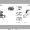
Landini Technofarm Europa Tier 3 2008-2015 rs51 80 Parts Catalog 4220708m4
20 USDSize: 20.06 MBFormat: PDFLanguage: EnglishBrand: LandiniType of Machine: TractorsType of Manual: Parts ManualModel: Landini Technofarm Europa Tier 3 rs51 80Part Number: 4220708m4Year: 2008-2015Number of Pages: 379 Pages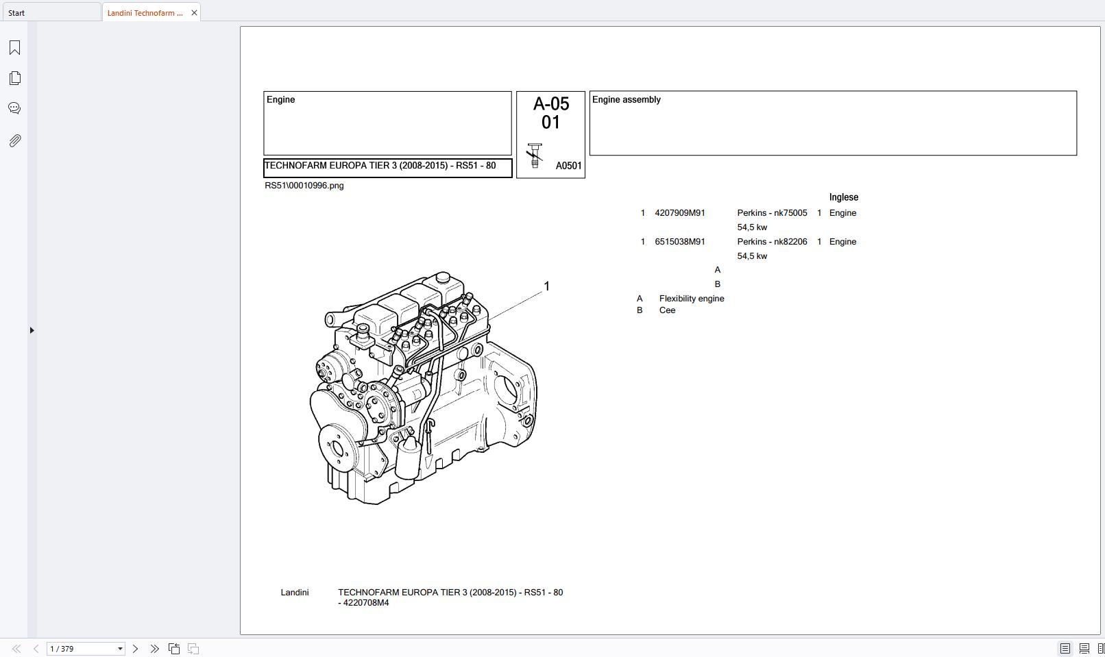
REALEASE :
REALEASE :
-
Landini Tractor Serie 6L T4I (2014- ) RP76-6-160L Parts Catalog 6531289M1
20 USDSize: 32.96 MBFormat: PDFLanguage: EnglishBrand: LandiniType of Machine: TractorType of Manual: Parts CatalogModel: Serie 6L T4I (2014- ) RP76-6-160L TractorPart Number: 6531289M1Number of Pages: 525 Pages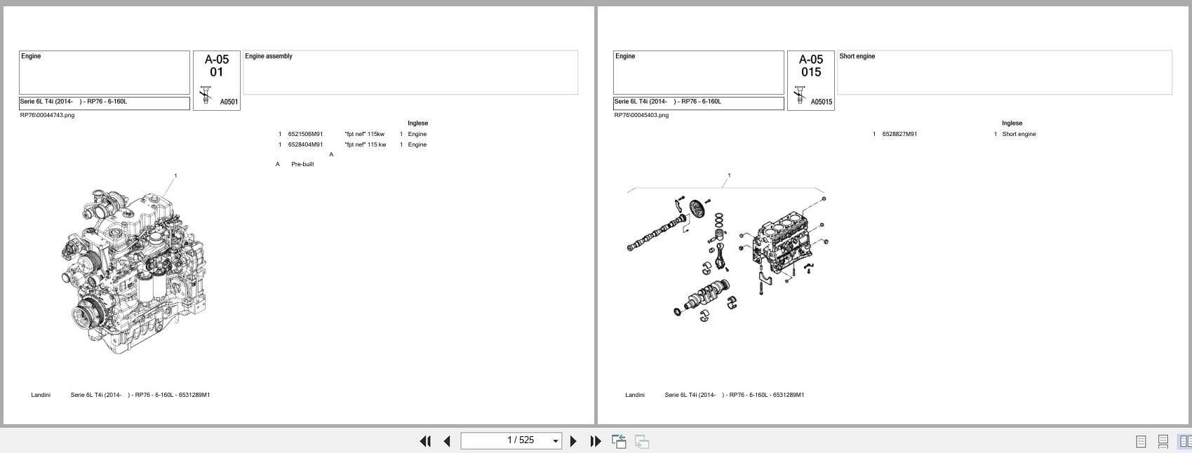
REALEASE :
REALEASE :
-
Landini Tractor Vision 85 95 105 Service Manual 3667238M3
30 USDSize: 33.24 MBFormat: PDFLanguage: EnglishBrand: LandiniType of Machine: TractorType of Manual: Service Manual, Electrical SchematicModel: Landini Vision 85 ; Vision 95 ; Vision 105 TractorEngine:Perkins 1104C-44 Diesel Engine – Vision 85 TractorPerkins 1104C-44T Diesel Engine – Vision 95 ; Vision 105 TractorPart Number: 3667238M3Number of Pages: 1084 Pages
REALEASE :
REALEASE :
-
Landini Tractor Trekker3 3-085 Compact S CT04 Operators Manual 6735122A1 2024
50 USDSize: 60.82 MBFormat: PDFLanguage: EnglishBrand: LandiniType of Machine: TractorType of Manual: Operators ManualModel: Landini Trekker3 3-085 Compact ; Trekker3 3-085 Compact S TractorEngine: Kohler KDI 2504 TCR EnginePart Number: 6735122A1Publication Date: 2024Number of Pages: 268 Pages
REALEASE :
REALEASE :
-
Landini Tractor Technofarm 60 70 80 75 SpeedFour RS50 Operators And Maintenance Manual 3696315M1 2007
10 USDSize: 9.06 MBFormat: PDFLanguage: EnglishBrand: LandiniType of Machine: TractorType of Manual: Operators And Maintenance ManualModel: Landini TractorTechnofarm 60 SpeedFour ; Technofarm 70 SpeedFourTechnofarm 80 SpeedFour ; Technofarm 75 SpeedFourEngine: Perkins Diesel Engine1103C-33 – Technofarm 60 SpeedFour Tractor1103C-33T – Technofarm 70 SpeedFour ; Technofarm 80 SpeedFour Tractor1104C-44 – Technofarm 75 SpeedFour TractorPart Number: 3696315M1Publication Date: 2007Number of Pages: 158 Pages
REALEASE :
REALEASE :
-
Landini Tractor Rex Tier 3 (2008-2009) RP53 90 F_GE_GT Parts Catalog 4216183M1
30 USDSize: 36.82 MBFormat: PDFLanguage: EnglishBrand: LandiniType of Machine: TractorType of Manual: Parts CatalogModel: Landini Rex Tier 3 (2008-2009) RP53 90 F/GE/GT TractorPart Number: 4216183M1Number of Pages: 801 Pages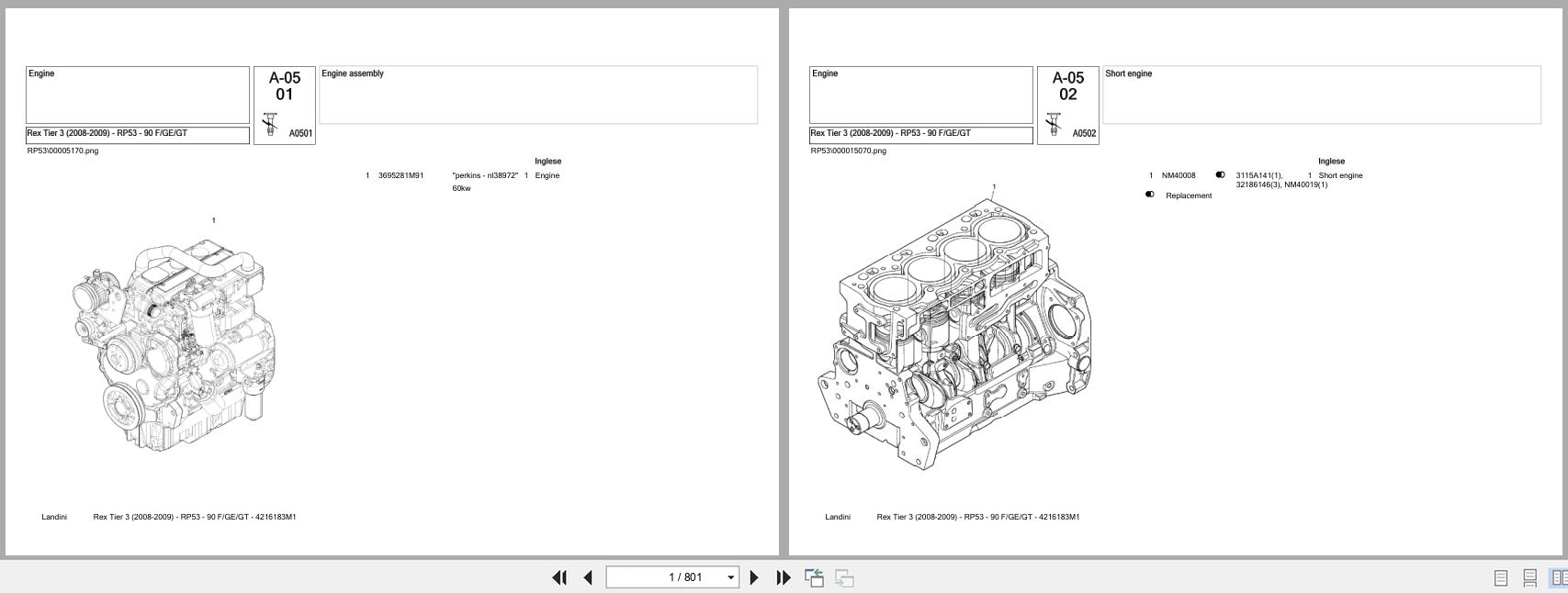
REALEASE :
REALEASE :