
1 ITEMVIEW CART

Total: 180.00

Expert Support
Full Speed
100% Working
180 USD
Contents:
– 7 Series Robo-Six Active
Introduction
Liability
Purpose Of The Manual
Copyright
Table Of Contents
– 1001 – Safety
Introduction
Technical Notes
Maintain The Tractor In A Safe Way
Danger Signs
Tightening Torques
– 1002 – Specific Equipment Catalogue
Specific Equipment
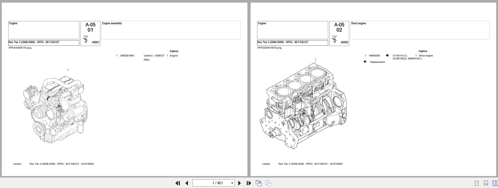
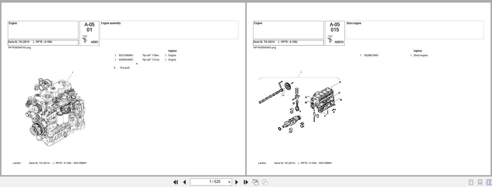
– 2 – Engine
Technical Specifications
Annexes
– 2002 – Exhaust Gases Treatment System
Technical Specifications
Safety
Ats System
Adblue®
– 2003 – Engine Removal
Technical Specifications
Safety
Engine
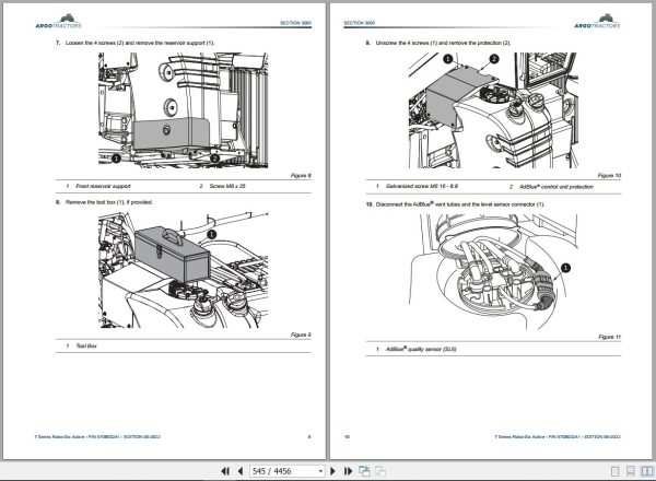
– 3005 – Fuel Tank
Technical Specifications
Safety
Procedures
– 4001 – Electric System
Technical Specifications
Safety
Fuses And Relays
Operator’s Interface Overview
Sockets Overview
Lights Overview
Component Sheets
Wiring Harnesses Locations
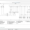
Wiring Diagrams
Complete List Of Connections
– 4002 – Instrument Cluster Set-Up And Calibrations
General Instrument Cluster Specifications
Calibration From The Instrument Cluster
Calibration From The Instrument The Diagnostic Tool
– 5 – Steering System – Operation
Power Steering System
Description Of The Hydraulic System
– 5001 – Steering Column And Power Steering System
Technical Specifications
Sections And Perspective Views
Safety
Steering Column And Power Steering System
– 6 – Transmission – Operation
Transmission
Annexes
– 6021 – Front Axle
Technical Specifications
Safety
Front Axle
Annexes
– 6025 – Front Hitch And Pto
Technical Specifications
Sections And Perspective Views
Safety
Front Hitch Maintenance
Front Pto Service
– 7 – Brakes – Operation
Brake Circuit
Hydraulic Trailer Brake
Trailer Brake System Eec Type
Trailer Brake System Of The Italy “Cuna†Type
Trailer Brake System Eu Type 2015/68
Brake Bleed Nipples
On-Off Valve
Trailer Air Brakes
Iso And Functional Diagrams – Air Braking System
System Components
Troubleshooting
Diagnostic Tests Of The Air System
– 7003 – Adjustments And Inspections
Safety
Brakes
“Pick-Up Hitchâ€
– 8 – Hydraulic Components – Operation
Technical Specifications
Hydraulic Circuit
Hydraulic Pumps
Powershift Clutches Management Control Unit
Ranges Management Control Unit
Cut-Off Valve
Dynamic Priority Valve
Hydraulic Manifolds
Power Steering System
Cooling System By-Pass Valve
Hydraulic Trailer Braking
Rear Auxiliary Control Valves
Hydraulic Suspension Cab
Suspended Axle
Front Hitch
Midmount Control Valve
Rear Hydraulic Unions
Transmission Breather And Oil Fill
– 8001 – Troubleshooting Of The Hydraulic System
Troubleshooting
Hydraulic System Diagnostic Testing
– 8003 – Piston Pump
Technical Specifications
Safety
Procedure For Piston Pump
– 9 – Cab
Technical Specifications
Air Conditioning System
Compressor
Condenser
Evaporator
Air Conditioning Pressure Switch
Air Conditioning Control Panel
– 9001 – Cab Adjustments
Technical Specifications
Safety
Cab
– 9002 – Cab Removal
Technical Specifications
Safety
Cab
– 9004 – Air Conditioning System
Safety
Electrical System Maintenance
Pressure Tests
Troubleshooting
– 9005 – Operator Seat
Safety
Description
Annexes
– 10000 – Control Units Alarms Diagnostics
Can Bus System
Error Handling Via Can
Instrument Cluster Control Unit Ec1
Engine Control Unit Ec6
Hitch Control Unit Ec9
Suspended Axle Control Unit Ec10
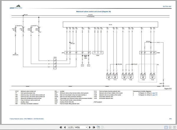
Midmount Valves Control Unit Ec16
Gps Antenna Ec27
Electronic Power Steering Control Unit Ec28
Satellite Autoguide Monitor X25 Ec31
Dashboard Control Unit Ec32
Trailer Brake Control Unit Ec35
Transmission Control Unit Ec40
Suspended Cab Control Unit And Isobus Ec43

REALEASE :
REALEASE :

REALEASE :
REALEASE :
REALEASE :
REALEASE :

REALEASE :
REALEASE :

REALEASE :
REALEASE :
REALEASE :
REALEASE :
REALEASE :
REALEASE :

REALEASE :
REALEASE :
Automotive - Heavy Equipment - Truck & Bus - Forklift - Crane