
0 ITEMSVIEW CART

✓
Expert Support
✓
Full Speed
✓
100% Working
Landini Tractor 8-270 8-310 V-SHIFT Service Manual 6723914A1 EN
Size: 586.17 MB
Format: PDF
Language: English
Brand: Landini
Type of Machine: Tractor
Type of Manual: Service Manual, Hydraulic and Electrical Diagrams
Model: Landini 8 V-SHIFT Series Tractor
8-270 V-SHIFT, 8-310 V-SHIFT
Part Number: 6723914A1
Publication Date: 2023
Number of Pages: 4810 Pages
200 USD
- Description
Description
Contents:
– Series 8 V-Shift
Introduction
Liability
Purpose Of The Manual
Copyright
Table Of Contents
– 1001 – Safety
Introduction
Technical Notes
Maintain The Tractor In A Safe Way
Danger Signs
Tightening Torques
– 2000 – Engine
Technical Specifications
Annexes
– 2002 – Exhaust Gas Treatment System
Technical Specifications
Safety
Ats System
Adblue®
– 3004 – Other Tanks
Adblue® Fluid Tank
– 3005 – Fuel Tank
Fuel Tank
– 4001 – Electric System
Technical Specifications
Safety
Fuses And Relays
Component Sheets
Wiring Harnesses Locations
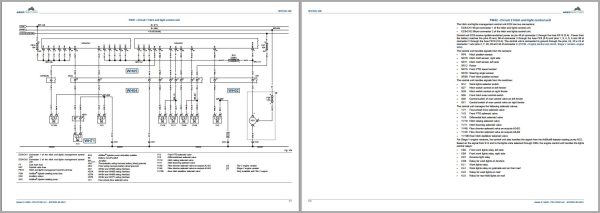
Wiring Diagrams
– 4002 – Instrument Cluster Control Unit Setup And Calibrations
Instrument Cluster Set-Up
Calibration From The Instrument Cluster
Calibrations With The Diagnostic Tool
– 5000 – Steering System – Operation
Power Steering System
Description Of The Hydraulic System
Power Steering System Operation
– 6000 – Transmission
General Information
Location Of Main Transmission Components
Hydrostatic Unit
Mechanic Unit
General Operating Principle
Annexes
– 6001 – Engine – Transmission Coupling
Torsional Coupling
– 6021 – Front Axle
Front Axle
Annexes
– 6025 – Front Hitch And Pto
Sections And Perspective Views
– 7000 – Brakes – Operation
Brake Circuit
Hydraulic Trailer Brake
Trailer Brake System, Eec Type
Trailer Brake System Of The Italy “Cuna†Type
Distribution Valve
Trailer Air Brakes
Iso And Functional Diagrams – Air Braking System
System Components
Troubleshooting For Air System
Diagnostic Tests Of The Air System
– 7003 – Brakes – Overhaul And Adjustments
Safety
Brakes
– 8000 – Hydraulic Circuit – Operation
Technical Specifications
Hydraulic Circuit
Hydraulic Pumps
Pressure Control Power Pack
Clutches Solenoid Valves Unit
Hydrostatic Unit
Cut-Off Valve
Hydraulic Manifolds
Oil-To-Oil Heat Exchanger
Electronic Power Steering
Hydraulic Trailer Braking
Rear Control Valves
Suspended Cab
Suspended Axle
Front Hitch
Midmount Control Valve
“Power Beyondâ€
Transmission Breather And Oil Filling
– 8001 – Troubleshooting For The Hydraulic System
Troubleshooting
Hydraulic System Diagnostic Testing
– 9004 – Chassis And Mounted Implements
Safety
Technical Specifications
Air Conditioning System
Heating, Ventilation And Conditioning Unit
Compressor
Condenser
Evaporator
Air Conditioning Pressure Switch
Mixed Air Temperature Sensor
Cab External Temperature Sensor
Cab Inner Temperature Sensor
Sun Radiation Sensor
Air Conditioning Control Panel
Electrical System Maintenance
Pressure Tests
Troubleshooting
– 9005 – Operator Seat
Safety
Description
Annexes
– 10000 – Diagnostics
Can Bus System
Error Handling Via Can
Instrument Cluster Control Unit Ec1
Transmission Control Unit Ec4
Engine Control Unit Ec6 – Engine Version Tier 2
Engine Control Unit Ec6 – Stage V Engine Version
Hitch And Lights Management Control Unit Ec9
Armrest Control Unit Ec15
Midmount Valves Control Unit Ec16
Air Conditioning Control Unit Ec17
Vehicle Vdc Control Unit Ec23
Gps Antenna Ec27
Electronic Power Steering Control Unit Ec28
Satellite Autoguide Monitor X25 Ec31
Trailer Braking Control Unit Ec35
Telematics Control Unit Ec41
Suspended Cab, Suspended Axle And Isobus Control Unit Ec43
– 11000 – Disassembly Procedures
Safety
Front Hitch And Pto
Front Axle
Tanks And Reservoirs
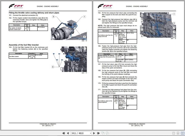
Engine
Steering Column
Rear Hitch
Cab
Transmission
– Annexes
Engine Manual
Transmission Manual
Front Axle Manual
Operator’s Seat Manual
Related Products
-
Landini Tractor Trekker4 4-085 To 4-120 F-M CP05 Operators Manual 6696772A2 2022
30 USDSize: 86.85 MBFormat: PDFLanguage: EnglishBrand: LandiniType of Machine: TractorType of Manual: Operators ManualModel: Landini Trekker4 Series Tractor4-085 F ; 4-095 F ; 4-105 F ; 4-110 F ; 4-120 F4-085 M ; 4-095 M ; 4-105 M ; 4-110 M ; 4-120 MEngine:Deutz-AG TCD 2.9 L4 HT Engine – 4-085 TractorDeutz-AG TCD 2.9 L4 Hp Engine – 4-095 ; 4-105 ; 4-110 ; 4-120 TractorPart Number: 6696772A2Publication Date: 2022Number of Pages: 310 Pages
REALEASE :
REALEASE :
-
Landini Tractor Technofarm 60 70 80 75 SpeedFour RS50 Operators And Maintenance Manual 3696315M1 2007
10 USDSize: 9.06 MBFormat: PDFLanguage: EnglishBrand: LandiniType of Machine: TractorType of Manual: Operators And Maintenance ManualModel: Landini TractorTechnofarm 60 SpeedFour ; Technofarm 70 SpeedFourTechnofarm 80 SpeedFour ; Technofarm 75 SpeedFourEngine: Perkins Diesel Engine1103C-33 – Technofarm 60 SpeedFour Tractor1103C-33T – Technofarm 70 SpeedFour ; Technofarm 80 SpeedFour Tractor1104C-44 – Technofarm 75 SpeedFour TractorPart Number: 3696315M1Publication Date: 2007Number of Pages: 158 Pages
REALEASE :
REALEASE :
-
Landini Tractor Trekker3 3-085 Compact S CT04 Operators Manual 6735122A1 2024
50 USDSize: 60.82 MBFormat: PDFLanguage: EnglishBrand: LandiniType of Machine: TractorType of Manual: Operators ManualModel: Landini Trekker3 3-085 Compact ; Trekker3 3-085 Compact S TractorEngine: Kohler KDI 2504 TCR EnginePart Number: 6735122A1Publication Date: 2024Number of Pages: 268 Pages
REALEASE :
REALEASE :
-
Landini Tractor Serie 6L T4I (2014- ) RP76-6-160L Parts Catalog 6531289M1
20 USDSize: 32.96 MBFormat: PDFLanguage: EnglishBrand: LandiniType of Machine: TractorType of Manual: Parts CatalogModel: Serie 6L T4I (2014- ) RP76-6-160L TractorPart Number: 6531289M1Number of Pages: 525 Pages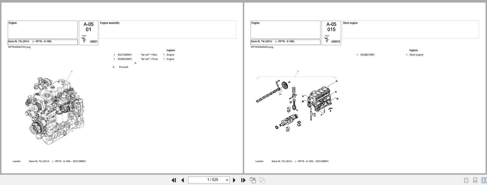
REALEASE :
REALEASE :
-
Landini Tractor Trekker 4-105 To 4-110 FM CP04 Operators Manual 6621074A4 2021
20 USDSize: 32.41 MBFormat: PDFLanguage: EnglishBrand: LandiniType of Machine: TractorType of Manual: Operators ManualModel: Landini TractorTrekker 4-105 STD ; Trekker 4-115 STDTrekker 4-085 F/M ; Trekker 4-095 F/MTrekker 4-105 F/M ; Trekker 4-110 F/MEngine:Deutz C4DT69 Engine – Trekker 4-105 STDDeutz C4DT74 Engine – Trekker 4-115 STDDeutz 2.9 TCD L4 Stage 5 Engine – Trekker 4-085 F/MDeutz 2.9 TCD L4 Engine – Trekker 4-095 ; 4-105 ; 4-110 F/MPart Number: 6621074A4Publication Date: 2021Number of Pages: 290 Pages
REALEASE :
REALEASE :
-
Landini Technofarm Europa Tier 3 2008-2015 rs51 80 Parts Catalog 4220708m4
20 USDSize: 20.06 MBFormat: PDFLanguage: EnglishBrand: LandiniType of Machine: TractorsType of Manual: Parts ManualModel: Landini Technofarm Europa Tier 3 rs51 80Part Number: 4220708m4Year: 2008-2015Number of Pages: 379 Pages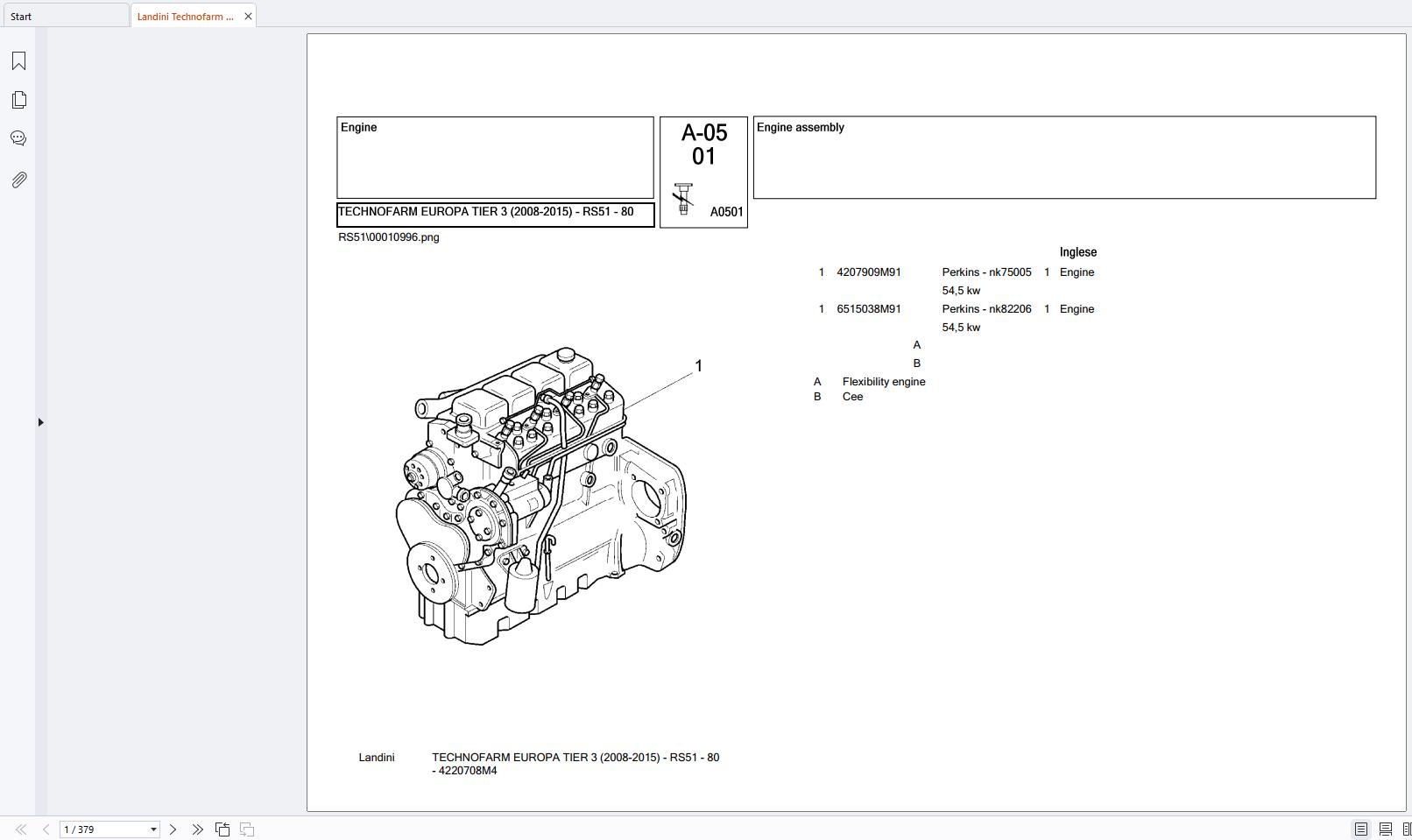
REALEASE :
REALEASE :
-
Landini Tractor Vision 85 95 105 Service Manual 3667238M3
30 USDSize: 33.24 MBFormat: PDFLanguage: EnglishBrand: LandiniType of Machine: TractorType of Manual: Service Manual, Electrical SchematicModel: Landini Vision 85 ; Vision 95 ; Vision 105 TractorEngine:Perkins 1104C-44 Diesel Engine – Vision 85 TractorPerkins 1104C-44T Diesel Engine – Vision 95 ; Vision 105 TractorPart Number: 3667238M3Number of Pages: 1084 Pages
REALEASE :
REALEASE :
-
Landini Tractor Rex Tier 3 (2008-2009) RP53 90 F_GE_GT Parts Catalog 4216183M1
30 USDSize: 36.82 MBFormat: PDFLanguage: EnglishBrand: LandiniType of Machine: TractorType of Manual: Parts CatalogModel: Landini Rex Tier 3 (2008-2009) RP53 90 F/GE/GT TractorPart Number: 4216183M1Number of Pages: 801 Pages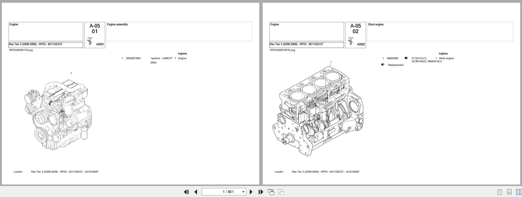
REALEASE :
REALEASE :