
1 ITEMVIEW CART

Total: 110.00


Expert Support
Full Speed
100% Working
100 USD
List of Files:
LTM1070-1 016056 -016061 Carrier Service Manual EN.pdf
Summary of components
Technical data
Hydropneumatic Brake System
Circuit diagram
Functional components
Functional diagram – air supply
Functional description – air supply
Functional diagram – service brake system
Functional description – service brake system
Functional diagram – auxiliary consumers
Functional description – auxiliary consumers
Testing and adjusting
Bleeding the hydraulic brake system
Hydraulic Steering System
Circuit diagram
Functional components
Functional diagram – semi intergral power steering
Functional description – semi intergral power steering
Functional diagram – servostat steering
Functional description – servostat steering
Testing and adjusting ( hydraulic )
Testing and adjusting ( mechanic )
Hydraulic Supperting System and Rear Wheel Steering
Circuit diagram
Functional components
Functional diagram – supports
Functional description – support
Functional diagram – rear wheel steering
Functional description — rear wheel steering
Testing and adjusting
Hydropneumatic Suspension
Circuit diagram, hydraulic
Functional components
Functional diagram
Functional description
Description of suspension programs
Testing and adjusting
Arrangement – proximity switch
Circuit diagram, electric
Functional description, electric (suspension)
Electrical Installation
Circuit diagram – supporting system
Circuit diagram – undercarriage / superstructure
Key to symbols
LTM1070-1 Carrier Service Manual EN.pdf
Comments on crane type L TM 1070
General arrangement – carrier (fig. 1)
Arrangement – power shift gear (fig. 1.1 )
l. brake system
Position of fig. 2 to 2.7
Description, separator with automatic draw-off valve
-on for cranes of series 0-24 u tooo 16 168
Circuit diagram – air supply and brake system sheet I
Summary of components to sheet 1
Circuit diagram -secondary consumers, carrier / sheet 2
Summary of components to sheet 2
Circuit diagram – secondary consumers, carrier – superstructure / sheet 3
Summary of components to sheet 3
LTM1070-1 Carrier UW Service Manual EN.pdf
UW-01 General
UW-02 General drawing
UW-03 Technical description
UW-04 Drive unit/ Diesel engine
UW-05 Cooling sysm,/Ventilator drive
UW-06 Automatic transmission
UW-07 Transfer case/Cardan shafts
UW-08 Axles with add-on components
UW-09 Air and braking system
UW-10 Steering system
UW-11 Outrigger/rear axle steering
UW-12 Axle-suspension system
UW-13 Electric system
UW-14 Additional units
UW-15 Miscellaneous
LTM1070-1 Service Manual DE.pdf
LTM1070-1 Service Manual EN.pdf
Technical description
Summary of components
Chassis
Technical data
Chassis
Superstructure
Removing and installing components
Diesel engine
Summary Of comiXjnents
Removing and installing, engine
Removing and installing, add-on parts
Gear
Summary of
Removing and installing, gear
Removing and installing, add-on parts
Transfer box
Summary of coml.»nents
Removing and installing, transfer
Removing and installing, add-on parts
Propeller shafts
Summary of components
Removing and installing
Axles
Summary of
Removing and installing, axles
Removing and installing, add-on parts
Steering
Summary of components
Removing and installing, steering
Removing and installing, add-on parts
Supports f Suspension
Summary of cormxments
Removing and installing, sliding arms
Removing and installing, supporting rams / outrigger rams
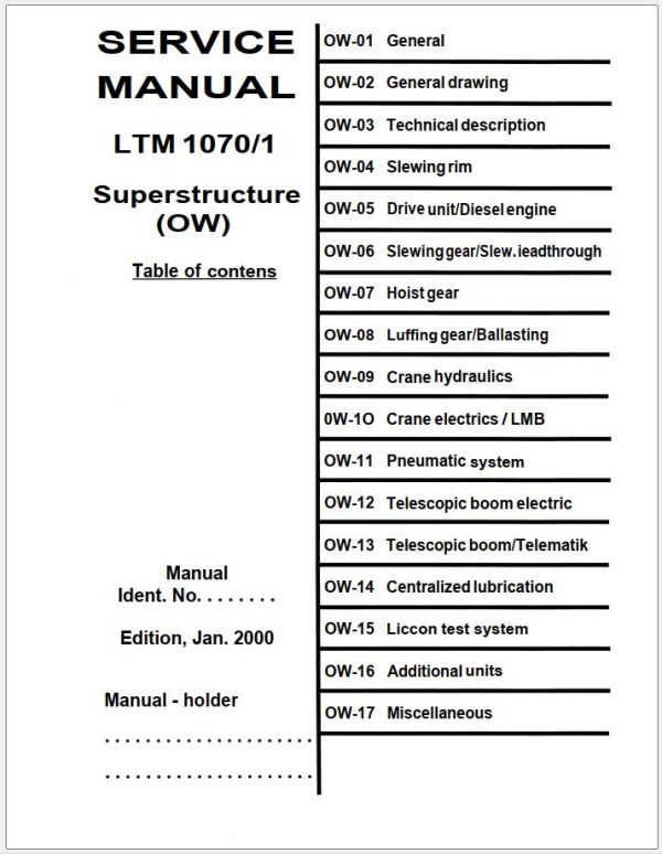
LTM1070-1 Superstructure OW Service Manual EN.pdf
OW-01 General
OW-02 General drawing
OW-03 Technical description
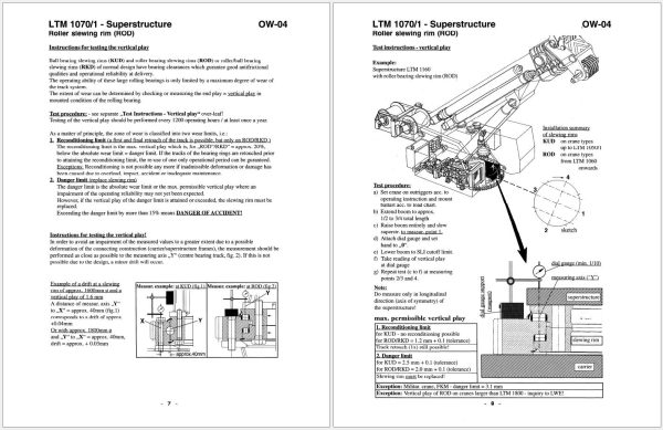
OW-04 Slewing rim
OW-05 Drive unit/Diesel engine
OW-06 Slewinggear/Slew.ieadthrough
OW-07 Hoist gear
OW-08 Luffing gear/Ballasting
OW-09 Crane hydraulics
0W-1O Crane electrics / LMB
OW-11 Pneumatic system
OW-12 Telescopic boom electric
OW-13 Telescopic boom/Telematik
OW-14 Centralized lubrication
OW-15 Liccon test system
OW-16 Additional units
OW-17 Miscellaneous
LTM1070-1 Superstructure Service Manual EN.pdf
Comments on crane type L TM 1070
General arrangement – superstructure (fig. 1 )
Position of components ( photographs for summary ) fig. 2 to 14
Crane hydraulics, general
Functional diagram – example ( hoist gear )
Functional description
Comments on crane operation
Crane hydraulics for cranes from series 0-29.1 ( up to 00 16 219 )
Circuit diagram – complete ( with hoist gear ( HG ) II 3332-970.2.1 (23)
Summary of components to circuit diagram
Crane hydraulics at I-winch version
Arrangement — stand
Diagram – supply and pilot control I sheet 1
Functional outline to sheet 1
Diagram – hoist gear I I sheet 2
Functional outline to sheet 2
Diagram – luffing gear I sheet 3
Functional outline to sheet 3
Diagram – telescnping gear I sheet 4
Functional outline to sheet 4
Diagram – slewing gear / sheet 5
Functional outline to sheet 5
Diagram – ballasting ( interlocking device — superstructure ) / sheet 6
Functional outline to sheet 6
Crane hydraulics at 2-winch version
Arrangement – stand
Diagram – supply and pilot control I sheet 1
Functional outline to sheet 1
Diagram – hoist gear I at winch selector switch pos. I or II/ sheet 2
Functional outline to sheet 2
Diagram – hoist gear II at winch selector switch position II / sheet 3
Functional outline to sheet 3
Diagram – hoist gear II at winch selector switch Ill / sheet 4
Functional outline to sheet 4
Diagram – luffing gear at winch selector switch I or Ill shæt 5
Functional outline to sheet 5
Diagram – telescopic gear at winch selector switch pos. I or Ill / sheet 6
Functional outline to sheet 6
Diagram – slewing gear / sheet 7
Functional outline to sheet 7
Diagram – ballasting ( interlocking device —superstructure ) / sheet 8
Functional outline to sheet 8
Crane hydraulics for cranes from series 29.2 from m16220
Circuit diagram – complete ( with hoist gear II ) 3332-970.25
Summary of components to circuit diagram
Crane hydraulics at I-winch version
Arrangement — stand
Diagram – supply and pilot control / sheet 1
Functional outline to sheet 1
Diagram – hoist gear I / sheet 2
Functional outline to sheet 2
Diagram – luffing gear I sheet 3
Functional outline to sheet 3
Diagram – telescoping gear I sheet 4
Functional outline to sheet 4
Diagram – slewing gear / sheet 5
Functional outline to sheet 5
Diagram – ballasting / sheet 6
Functional outline to sheet 6
Crane hydraulics at 2-winch version
Arrangement – operator’s stand
Diagram – supply and pilot control / sheet 1
Functional outline to sheet I
Diagram – hoist gear I at winch selector switch pos. I or II / sheet 2
Functional outline to sheet 2
Diagram – hoist gear II at winch selector switch position II / sheet 3
Functional outline to sheet 3
Diagram – hoist gear II at winch selector switch position Ill I sheet 4
Functional outline to sheet 4
Diagram – luffing gear at winch selector switch pose I or III / sheet 5
Functional outline to sheet 5
Diagram – telescopic gear at winch selector switch pos. I or III / sheet 6
Functional outline to sheet 6
Diagram – slewing gear / sheet 7
Functional outline to sheet 7
Diagram- ballasting I sheet 8
Functional outline to sheet 8
Crane electric for cranes of series O to 13 u to 00 16 088
Circuit diagram – crane control with 1 hoist gear
Circuit diagram – crane control with 2 hoist gears
Circuit diagram – electrics, superstructure
Key to for circuit diagram
Crane electric for cranes from series 14 ( from 00 16 089 )
Circuit diagram ( with Liccon ) — version for hoist gear I + II
Key to
Key to for circuit diagram
Summary of subassemblies
Plan of terminals
Arrangement — input board and fuses
Arrangement — switch cabinet
LTM1070-1 Technical Information DE FR.pdf
REALEASE :

REALEASE :
21.10.2022
REALEASE :
21.10.2022

REALEASE :
23.09.2022
REALEASE :
23.09.2022

REALEASE :
21.10.2022
REALEASE :
21.10.2022

REALEASE :
03.12.2022
REALEASE :
03.12.2022

REALEASE :
21.10.2022
REALEASE :
21.10.2022

REALEASE :
21.10.2022
REALEASE :
21.10.2022

REALEASE :
13.07.2022
REALEASE :
13.07.2022
 Automotive - Heavy Equipment - Truck & Bus - Forklift - Crane