
0 ITEMSVIEW CART

✓
Expert Support
✓
Full Speed
✓
100% Working
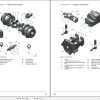
Liebherr Crawler Dozer PR776-1296 Service Manual 12254329
Size: 64.09 MB
Format: PDF
Language: English
Brand: Liebherr
Type of Machine: Crawler Dozer
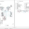
Type of Manual: Service Manual, Electric and Hydraulic Diagrams
Model: Liebherr PR776-1296 Crawler Dozer
Order Number: 12254329
Publication Date: 2023
Number of Pages: 908 Pages
150 USD
- Description
Description
Contents:
010 Introduction
010.1 Safety instructions
010.2 Special tools for maintenance and repair work
010.3 Standards and specifications
010.4 Conservation guidelines
010.5 Repair welding
010.6 Hydraulic symbols
010.7 Electrical symbols
010.8 Material weights
020 Technical data
020.1 Complete machine
020.2 Drive group
020.3 Cooling system
020.4 Working hydraulics
020.5 Travel hydraulics
020.6 Hydraulic components
020.7 Electrical system
020.8 Travel gearbox
020.9 Travel gear, axles, tyres, drive shafts
020.10 Working attachment
030 Maintenance
030.1 Maintenance and inspection schedule
030.2 Fill quantities and lubrication chart
030.3 Lubricants and fuels
030.4 Maintenance tasks
030.5 Adjustment checklist
030.6 Adjustment procedure
040 Drive group
040.1 Diesel engine
040.2 Clutch
040.3 Splitter box
050 Cooling system
050.1 Complete cooling system
050.2 Cooler arrangement
050.3 Hydraulic
050.4 Cooling system – Full overview
060 Working hydraulics
060.1 Working hydraulics – Full overview
060.2 Regulating pump
060.3 Proportional control valve block
060.4 Working hydraulic pilot control unit
060.5 Hydraulic cylinder
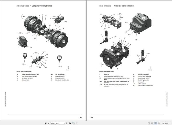
070 Travel hydraulics
070.1 Complete travel hydraulics
070.2 Travel hydraulics – Full overview
070.3 Regulating pump
070.4 Variable displacement pump
070.5 Variable displacement motors
070.6 Distributor block
080 Hydraulic components
080.1 Hydraulic cylinder
080.2 Valves
080.3 Hydraulic tank
100 Brake system
100.1 Inching brake pedal
110 Electrical system
110.1 Electrical system – Full overview
110.2 Lighting system
110.3 Circuit diagrams
110.4 Electrical components of operator’s cab
110.5 Electrical components – Heatable exterior mirror (option)
110.6 Electrical components – Diesel engine
110.7 Diesel engine electrical components
110.8 Electrical components – Main frame
110.9 Electrical components – Main frame
110.10 Electrical components Compartments
110.11 Display unit
110.12 Electrical components LiDAT (option)
110.13 Electrical components LiTU3 (option)
110.14 Electrical components – Incline alarm (option)
110.15 Electrical components – Data interface (option)
110.16 Electrical components – Input module A240 (option)
110.17 Electrical components – Output module A135 (option)
110.18 Electrical components – Travel hydraulics pressure cut-off
110.19 Electrical components – Acoustic reversing warning device (option)
110.20 Electrical components – Disengageable reversing warning device (option)
110.21 Electrical components – Optical reversing warning device (option)
110.22 Electrical components – Engine after-run
110.23 Electrical components – Access ladder
110.24 Electrical components – Warm water heating device (option)
110.25 Electrical components – Jump-start (option)
110.26 Electrical components – Reversible fan drive (option)
110.27 Electrical components – Working hydraulics cutting angle adjustment (option)
110.28 Electrical components – 3-point belt with warning sound (option)
110.29 Electrical components – Supply box for external users (option)
110.30 Electrical components – Coolant level check (option)
110.31 Electrical components – External operating hour meter (option)
110.32 Electrical components – Generator disconnecting switch (option)
110.33 Electrical components – Ripper headlight (option)
120 Travel gearbox
120.1 Travel gear, overall
120.2 Brake system
120.3 Duo cone slipring seal
120.4 External oil supply
130 Travel gear, axles, tyres, drive shafts
130.1 Undercarriage frame
130.2 Idler
130.3 Tension unit
130.4 Track roller
130.5 Carrier roller (Optional)
130.6 Function, wear and evaluation
140 Steel components Basic machine
140.1 Lift cylinder suspension
140.2 Oscillating axle frame
140.3 Push frame
150 Working attachment
150.1 Semi U-blade
150.2 Hydraulic cutting angle adjustment
150.3 Ripper
150.4 Cutting angle adjustment – Ripper
160 Operator’s cab, heating and air conditioning
160.1 Operator’s platform
160.2 Operator’s cab
160.3 Heater and ventilation
160.4 Heating, ventilation, air conditioning
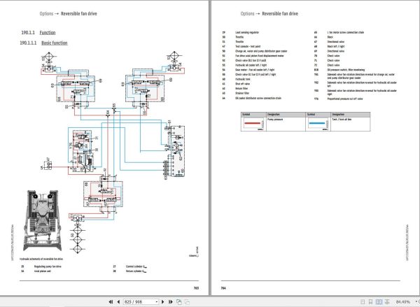
190 Options
190.1 Reversible fan drive
200 Service codes, diagnosis
200.1 Test and adjustment software
Related Products
-
Liebherr Crane HS HSG Operating Manual Spare Parts List Technical Information PDF DVD
Original price was: 1,500.540Current price is: 540. USDLiebherr Crane HS HSG Operating Manual Spare Parts Catalogue Technical Information DVD Size: 2.17 GB Fomat: PDF Language: EN,DE Brand: Liebherr Type of machine: Liebherr Crawler Crane Window: All Win 32 and 64 Bit, Mac OS Type of document: Liebherr Crane HS Operating Manual Liebherr Crane HS Spare Parts Catalogue Liebherr Crane HS Technical information Liebherr Crane HS Electrical Circuit Diagram Liebherr Crane HS Hydraulic Circuit DiagramHot-64%
REALEASE :
04.07.2022
REALEASE :
04.07.2022
-
LIEBHERR LTM 1095-5.1 95 Ton Operator Manual Diagnostics LICCON Wiring Schematic PDF
Original price was: 200.60Current price is: 60. USDLIEBHERR LTM 1095-5.1 95 Ton Operator Manual, Diagnostics LICCON & Wiring DiagramSize: 77.3 MBFormat: PDFlanguage: EnglishBrand: LiebherrType of machine: Mobile CraneType of document:Model: LIEBHERR LTM 1095-5.1DETAIL CONTENTS: “CLICK HERE“Hot-70%
REALEASE :
25.03.2022
REALEASE :
25.03.2022
-
Liebherr Mobile Crawler Cranes PDF Spare Parts List DVD
Original price was: 200.140Current price is: 140. USDLiebherr Mobile & Crawler Cranes 1.24 GB PDF Spare Parts Catalog DVDSize: 1.24 GBFormat: PDF, winrarBrand: LiebherrLanguages: English, Deutsch, Spanish, Russian, French, PortugueseType of Machine: Mobile Crane, Crawler Crane, Rough Terrain Crane, Tower CraneType of Document: Spare Parts CatalogsNumber of DVD: 1 DVDOS: Windows Vista, XP, 7, 8.1, 8, 10, MacOSHigh-Speed DownloadDETAIL CONTENTS: “CLICK HERE“Hot-30%
REALEASE :
29.03.2022
REALEASE :
29.03.2022
-
Liebherr Crawler Crane with Telescopic Boom LTR 1100 100 Ton Operator Manual Diagnostics LICCON Wiring Diagram
Original price was: 400.160Current price is: 160. USDLiebherr Crawler Crane with Telescopic Boom LTR 1100 100 Ton Operator Manual, Diagnostics LICCON & Wiring Diagram Size: 734 Mb Language: English_EN Format: PDF Model: LTR 1100 Capacity: 100 Ton SN: Z97542 Diesel Engine: D944 A7 DETAIL CONTENTS: “CLICK HERE“Hot-60%
REALEASE :
23.03.2022
REALEASE :
23.03.2022
-
Liebherr Mining Excavators 84.88Gb PDF Updated 01.2022 Service Manuals DVD
USDLiebherr Mining Excavators 84.88Gb PDF Updated 01.2022 Service Manuals DVDSize: 84.88 Gb (PDF Files)Type of vehicle: Mining ExcavatorsType of manual: Service ManualLanguage: EnglishBrand: LiebherrFormat: PDFUpdate: 01.2022OS: All WindowsAmount of DVD: 1 DVDREALEASE :
01.13.2022
-
Liebherr Wheeled and Crawler Excavators Updated 03.2022 Service Manuals DVD PDF
Original price was: 800.340Current price is: 340. USDLiebherr Wheeled and Crawler Excavators 48.3GB Updated 03.2022 Service Manuals DVD PDFSize: 48.3 GB (PDF Files)Format: PDFLanguage: EN, DEBrand: LiebherrDate Updated: 03.2022OS: All Windows 32 & 64bitType of Vehicle: Wheeled and Crawler ExcavatorsType of Document: Service ManualsHigh-Speed Link Download DETAIL CONTENTS: “CLICK HERE“Hot-58%
REALEASE :
02.03.2022
REALEASE :
02.03.2022
-
Liebherr Wheel Loader Updated 03.2022 Full Service Manuals DVD PDF
Original price was: 700.340Current price is: 340. USDLiebherr Wheel Loader 24.29GB Updated 03.2022 Full Service Manuals DVD PDFSize: 24.29 GB (PDF Files)Type of Vehicle: Wheel LoadersType of Document: Service ManualsFormat: PDFLanguage: EN, ZH, DEBrand: LiebherrDate Updated: 03.2022OS: All Windows 32 & 64 bitHigh-Speed Link DownloadDETAIL CONTENTS: “CLICK HERE“Hot-51%
REALEASE :
02.03.2022
REALEASE :
02.03.2022
-
Liebherr Crane LTM 1800 Service Manual Operators Manual Schematic
Original price was: 300.180Current price is: 180. USDThey are PDF Service Manual Operators Manual Schematic Manual, You need to use these to repair your vehicle.Hot-40%
REALEASE :
16.09.2022
REALEASE :
16.09.2022
