
0 ITEMSVIEW CART

✓
Expert Support
✓
Full Speed
✓
100% Working
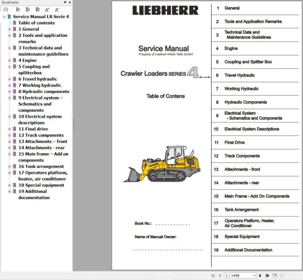
Liebherr Crawler Loaders LR624 LR634 Service Manual
Size: 134.00 MB
Format: PDF
Language: English
Brand: Liebherr
Type of Machine: Crawler Loaders
Type of Manual: Service Manual, Electric and Hydraulic Diagrams
Model: Liebherr LR624 LR634 Crawler Loaders
Engine: D934 S A6
Number of Pages: 1448 Pages
100 USD
- Description
Description
Contents:
1 General
Foreword and explanation
Safety guidelines
Service fluids
Table
Conservation guidelines
Material weights
2 Tools and application remarks
Special tools
Repair welding
Installation instructions
3 Technical data and maintenance guidelines
Technical data
Maintenance and inspection schedule
Maintenance and inspection guidelines
Quick reference for machine adjustment
Adjustment check list
4 Engine
Data page
Fan and cylinder arrangement
Installation kit Liebherr- Diesel particle filter
Installation and check list for Diesel particle filter
5 Coupling and splitterbox
Data page
Coupling
Splitterbox
Coupling – pump output
6 Travel hydraulic
Data page
Design
Function
Test and adjustment
Component arrangement
7 Working hydraulic
Data page
Design
Function
Test and adjustment
Component arrangement
8 Hydraulic components
Variable displacement pump
Variable displacement motor
Regulating pump – Working hydraulic
Constant pumps and motors
Pilot control
Control valve block
Valves
Hydraulic cylinder
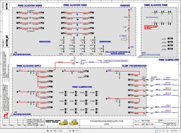
9 Electrical system – Schematics and components
Component description
Function list
Fuses, cross points, notes
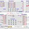
Current flow diagram
Instrument panel
Component arrangement – Electrical system
Travel joystick
Speed reduction pedal
10 Electrical system descriptions
Application software – travel drive
Software PDL – Diesel particle filter
Service Code List
11 Final drive
Data page
Design and function
Sectional view – final drive
12 Track components
Data page
Design, function, wear and evaluation
Test protocol and Wear chart
Track roller frame and idler unit
Track roller
Carrier roller
Tension unit
13 Attachments – front
4 in 1 Bucket
Bucket arm
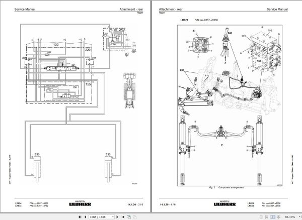
14 Attachments – rear
Ripper
15 Main frame – Add on components
Cooler arrangement
Hoist and tilt cylinder mount
Equalizer bar
Engine mount
16 Tank arrangement
Hydraulic tank
Fuel tank
Battery compartment
17 Operators platform, heater, air conditioner
Operators platform
Heater and Blower
Air conditioning system
Operator’s seat – air cushioned
Engine RPM adjustment
18 Special equipment
Refueling pump
Reversible fan
Rope winch
19 Additional documentation
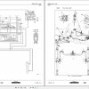
Schematics Travel hydraulic
Schematic Working hydraulic
Current Flow Diagram
Related Products
-
Liebherr Mining Excavators 84.88Gb PDF Updated 01.2022 Service Manuals DVD
USDLiebherr Mining Excavators 84.88Gb PDF Updated 01.2022 Service Manuals DVDSize: 84.88 Gb (PDF Files)Type of vehicle: Mining ExcavatorsType of manual: Service ManualLanguage: EnglishBrand: LiebherrFormat: PDFUpdate: 01.2022OS: All WindowsAmount of DVD: 1 DVDREALEASE :
01.13.2022
-
Liebherr Crawler Crane with Telescopic Boom LTR 1100 100 Ton Operator Manual Diagnostics LICCON Wiring Diagram
Original price was: 400.160Current price is: 160. USDLiebherr Crawler Crane with Telescopic Boom LTR 1100 100 Ton Operator Manual, Diagnostics LICCON & Wiring Diagram Size: 734 Mb Language: English_EN Format: PDF Model: LTR 1100 Capacity: 100 Ton SN: Z97542 Diesel Engine: D944 A7 DETAIL CONTENTS: “CLICK HERE“Hot-60%
REALEASE :
23.03.2022
REALEASE :
23.03.2022
-
LIEBHERR LTM 1095-5.1 95 Ton Operator Manual Diagnostics LICCON Wiring Schematic PDF
Original price was: 200.60Current price is: 60. USDLIEBHERR LTM 1095-5.1 95 Ton Operator Manual, Diagnostics LICCON & Wiring DiagramSize: 77.3 MBFormat: PDFlanguage: EnglishBrand: LiebherrType of machine: Mobile CraneType of document:Model: LIEBHERR LTM 1095-5.1DETAIL CONTENTS: “CLICK HERE“Hot-70%
REALEASE :
25.03.2022
REALEASE :
25.03.2022
-
Liebherr Wheeled and Crawler Excavators Updated 03.2022 Service Manuals DVD PDF
Original price was: 800.340Current price is: 340. USDLiebherr Wheeled and Crawler Excavators 48.3GB Updated 03.2022 Service Manuals DVD PDFSize: 48.3 GB (PDF Files)Format: PDFLanguage: EN, DEBrand: LiebherrDate Updated: 03.2022OS: All Windows 32 & 64bitType of Vehicle: Wheeled and Crawler ExcavatorsType of Document: Service ManualsHigh-Speed Link Download DETAIL CONTENTS: “CLICK HERE“Hot-58%
REALEASE :
02.03.2022
REALEASE :
02.03.2022
-
Liebherr Crane HS HSG Operating Manual Spare Parts List Technical Information PDF DVD
Original price was: 1,500.540Current price is: 540. USDLiebherr Crane HS HSG Operating Manual Spare Parts Catalogue Technical Information DVD Size: 2.17 GB Fomat: PDF Language: EN,DE Brand: Liebherr Type of machine: Liebherr Crawler Crane Window: All Win 32 and 64 Bit, Mac OS Type of document: Liebherr Crane HS Operating Manual Liebherr Crane HS Spare Parts Catalogue Liebherr Crane HS Technical information Liebherr Crane HS Electrical Circuit Diagram Liebherr Crane HS Hydraulic Circuit DiagramHot-64%
REALEASE :
04.07.2022
REALEASE :
04.07.2022
-
Liebherr Mobile Crawler Cranes PDF Spare Parts List DVD
Original price was: 200.140Current price is: 140. USDLiebherr Mobile & Crawler Cranes 1.24 GB PDF Spare Parts Catalog DVDSize: 1.24 GBFormat: PDF, winrarBrand: LiebherrLanguages: English, Deutsch, Spanish, Russian, French, PortugueseType of Machine: Mobile Crane, Crawler Crane, Rough Terrain Crane, Tower CraneType of Document: Spare Parts CatalogsNumber of DVD: 1 DVDOS: Windows Vista, XP, 7, 8.1, 8, 10, MacOSHigh-Speed DownloadDETAIL CONTENTS: “CLICK HERE“Hot-30%
REALEASE :
29.03.2022
REALEASE :
29.03.2022
-
Liebherr Crane LTM 1800 Service Manual Operators Manual Schematic
Original price was: 300.180Current price is: 180. USDThey are PDF Service Manual Operators Manual Schematic Manual, You need to use these to repair your vehicle.Hot-40%
REALEASE :
16.09.2022
REALEASE :
16.09.2022
-
Liebherr Wheel Loader Updated 03.2022 Full Service Manuals DVD PDF
Original price was: 700.340Current price is: 340. USDLiebherr Wheel Loader 24.29GB Updated 03.2022 Full Service Manuals DVD PDFSize: 24.29 GB (PDF Files)Type of Vehicle: Wheel LoadersType of Document: Service ManualsFormat: PDFLanguage: EN, ZH, DEBrand: LiebherrDate Updated: 03.2022OS: All Windows 32 & 64 bitHigh-Speed Link DownloadDETAIL CONTENTS: “CLICK HERE“Hot-51%
REALEASE :
02.03.2022
REALEASE :
02.03.2022
