
0 ITEMSVIEW CART

✓
Expert Support
✓
Full Speed
✓
100% Working
Liebherr Crawler Loaders PR712 to PR752 Service Manual
Size: 77.79 MB
Format: PDF
Language: English
Brand: Liebherr
Type of Machine: Crawler Loaders
Type of Manual: Service Manual, Electric and Hydraulic Diagrams
Model: Liebherr
PR 712 F/N xxx-0103→0500
PR 712B F/N xxx-0501→2999
PR 712B F/N xxx-3000→3083
PR 712B F/N xxx-3084→5599
PR 712B F/N xxx-5600→
PR 722 F/N xxx-0103→1000
PR 722B F/N xxx-1001→3000
PR 722B F/N xxx-3001→3170
PR 722B F/N xxx-3171→5599
PR 722B F/N xxx-5600→
PR 732 F/N xxx-2003→2500
PR 732B F/N xxx-2501→2999
PR 732B F/N xxx-3000→3135
PR 732B F/N xxx-3136→5599
PR 732B F/N xxx-5600→
PR 742 F/N xxx-2001→2500
PR 742B F/N xxx-2501→2999
PR 742B F/N xxx-3000→3088
PR 742B F/N xxx-3089→5233
PR 742B F/N xxx-5234→5599
PR 742B F/N xxx-5600→
PR 752 F/N xxx-2002→5599
PR 752 F/N xxx-5600→6199
PR 752 F/N xxx-6200→
Publication Date: 2009
Number of Pages: 1718 Pages
100 USD
- Description
Description
Contents:
1 General Information
Foreword and explanation
Safety guidelines
Hand signals
Service items
Table – charts
Code letters + terminal designations
2 Special Tools, Application Guidelines
Special tools
Repair welding
Installation guidelines
3 Technical Data – Maintenance Guidelines
Technical data
Maintenance and inspection guidelines
Maintenance and inspection instructions
Adjustment checklist and quick reference
4 Engine
Technical data LH engine
Power, torque LH engine
Fan and cylinder configuration LH Diesel engine
Remove and Install Engine fan
5 Coupling and Splitter Box
Technical data couling and splitter box
Coupling
Splitter box
6 Travel Hydraulic
Technical data
Description
Function / Schematics
Hydraulic hose routing
Test and adjustment
7 Working Hydraulic
Technical data
Description
Function / Schematics
Hydraulic hose routing
Test and adjustment
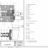
8 Hydraulic Components
Variable pump travel hydraulic
Variable motor travel hydraulic
Variable flow pump working hydraulic
Constant pumps and motors
Pilot control valve working hydraulic
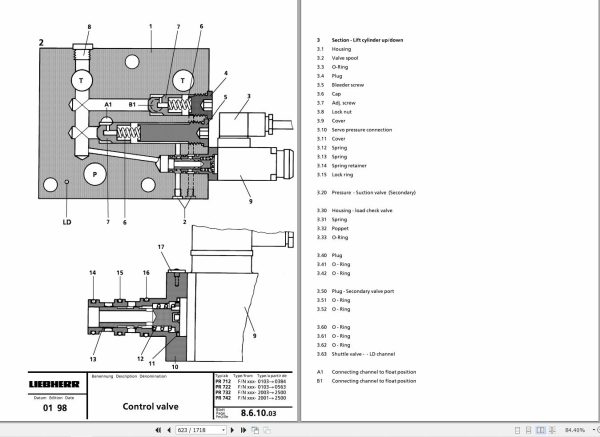
Control valve block
Valves
Hydraulic cylinder
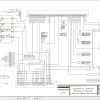
9 Electrical System
Current flow diagram
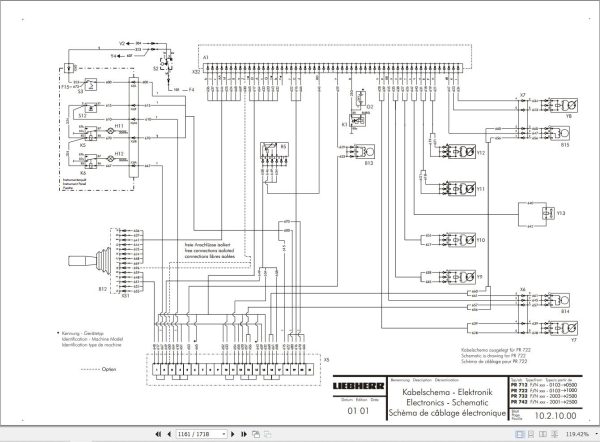
Electrical schematic and wiring
Instrument panel
Location of electrical components
10 Electronic Control
Electrical schematic and wiring
Description of function
Diagnostic test box application
Linkage Electronic engine speed sensing horsepower control system
Pedal control tester application
Travel control joystick
11 Travel Gear
Technical data
Construction, function travel gear
Remove and install
11.3.10 Travel gear type A
11.3.11 Travel gear type A
11.3.12 Travel gear type A
11.3.13 Travel gear type C
11.3.14 Travel gear type P
11.3.15 Travel gear type P-D
11.3.16 Travel gear type D
11.3.17 Travel gear type D
11.3.50 Travel gear PR 752
11.3.51 Travel gear PR 752
11.3.52 Travel gear PR 752
12 Track Components
Technical data
Description, function, wear effects
Measuring instructions and evaluation of wear
Appraisal report
Wear chart
Front idler
Track adjuster unit
Track roller
Carrier roller
Track roller frame
Support shaft preassembled
13 Attachments – front
Attachment – straight- / semi-U-blade
Attachment – 6-way-blade
14 Attachments – rear
Attachment – ripper
Attachment – cable winch
15 Main Frame – Add On Components
Cooler / radiator arrangement
Lift cylinder mount
Engine mounts
Equalizer bar
16 Tank Installation’s
Hydraulic tank
Fuel tank
Battery box
17 Operators Platform, Heater, Air Conditioner
Hydraulic tilting device
Heater and blower
Engine operation
Air conditioner
18 Special Attachments
Electrical schematic – canopy
Refueling pump
Electrical schematics – additional lights
Electrical schematics – additional heaters
Operator’s seat with air suspension
Hydraulic oil temperature gauge
Reversible fans
19 Miscellaneous Informations
Storage (preservation) guidelines
Material classification
Weight of materials
Related Products
-
LIEBHERR LTM 1095-5.1 95 Ton Operator Manual Diagnostics LICCON Wiring Schematic PDF
Original price was: 200.60Current price is: 60. USDLIEBHERR LTM 1095-5.1 95 Ton Operator Manual, Diagnostics LICCON & Wiring DiagramSize: 77.3 MBFormat: PDFlanguage: EnglishBrand: LiebherrType of machine: Mobile CraneType of document:Model: LIEBHERR LTM 1095-5.1DETAIL CONTENTS: “CLICK HERE“Hot-70%
REALEASE :
25.03.2022
REALEASE :
25.03.2022
-
Liebherr Mining Excavators 84.88Gb PDF Updated 01.2022 Service Manuals DVD
USDLiebherr Mining Excavators 84.88Gb PDF Updated 01.2022 Service Manuals DVDSize: 84.88 Gb (PDF Files)Type of vehicle: Mining ExcavatorsType of manual: Service ManualLanguage: EnglishBrand: LiebherrFormat: PDFUpdate: 01.2022OS: All WindowsAmount of DVD: 1 DVDREALEASE :
01.13.2022
-
Liebherr Mobile Crawler Cranes PDF Spare Parts List DVD
Original price was: 200.140Current price is: 140. USDLiebherr Mobile & Crawler Cranes 1.24 GB PDF Spare Parts Catalog DVDSize: 1.24 GBFormat: PDF, winrarBrand: LiebherrLanguages: English, Deutsch, Spanish, Russian, French, PortugueseType of Machine: Mobile Crane, Crawler Crane, Rough Terrain Crane, Tower CraneType of Document: Spare Parts CatalogsNumber of DVD: 1 DVDOS: Windows Vista, XP, 7, 8.1, 8, 10, MacOSHigh-Speed DownloadDETAIL CONTENTS: “CLICK HERE“Hot-30%
REALEASE :
29.03.2022
REALEASE :
29.03.2022
-
Liebherr Wheeled and Crawler Excavators Updated 03.2022 Service Manuals DVD PDF
Original price was: 800.340Current price is: 340. USDLiebherr Wheeled and Crawler Excavators 48.3GB Updated 03.2022 Service Manuals DVD PDFSize: 48.3 GB (PDF Files)Format: PDFLanguage: EN, DEBrand: LiebherrDate Updated: 03.2022OS: All Windows 32 & 64bitType of Vehicle: Wheeled and Crawler ExcavatorsType of Document: Service ManualsHigh-Speed Link Download DETAIL CONTENTS: “CLICK HERE“Hot-58%
REALEASE :
02.03.2022
REALEASE :
02.03.2022
-
Liebherr Wheel Loader Updated 03.2022 Full Service Manuals DVD PDF
Original price was: 700.340Current price is: 340. USDLiebherr Wheel Loader 24.29GB Updated 03.2022 Full Service Manuals DVD PDFSize: 24.29 GB (PDF Files)Type of Vehicle: Wheel LoadersType of Document: Service ManualsFormat: PDFLanguage: EN, ZH, DEBrand: LiebherrDate Updated: 03.2022OS: All Windows 32 & 64 bitHigh-Speed Link DownloadDETAIL CONTENTS: “CLICK HERE“Hot-51%
REALEASE :
02.03.2022
REALEASE :
02.03.2022
-
Liebherr Crawler Crane with Telescopic Boom LTR 1100 100 Ton Operator Manual Diagnostics LICCON Wiring Diagram
Original price was: 400.160Current price is: 160. USDLiebherr Crawler Crane with Telescopic Boom LTR 1100 100 Ton Operator Manual, Diagnostics LICCON & Wiring Diagram Size: 734 Mb Language: English_EN Format: PDF Model: LTR 1100 Capacity: 100 Ton SN: Z97542 Diesel Engine: D944 A7 DETAIL CONTENTS: “CLICK HERE“Hot-60%
REALEASE :
23.03.2022
REALEASE :
23.03.2022
-
Liebherr Crane LTM 1800 Service Manual Operators Manual Schematic
Original price was: 300.180Current price is: 180. USDThey are PDF Service Manual Operators Manual Schematic Manual, You need to use these to repair your vehicle.Hot-40%
REALEASE :
16.09.2022
REALEASE :
16.09.2022
-
Liebherr Crane HS HSG Operating Manual Spare Parts List Technical Information PDF DVD
Original price was: 1,500.540Current price is: 540. USDLiebherr Crane HS HSG Operating Manual Spare Parts Catalogue Technical Information DVD Size: 2.17 GB Fomat: PDF Language: EN,DE Brand: Liebherr Type of machine: Liebherr Crawler Crane Window: All Win 32 and 64 Bit, Mac OS Type of document: Liebherr Crane HS Operating Manual Liebherr Crane HS Spare Parts Catalogue Liebherr Crane HS Technical information Liebherr Crane HS Electrical Circuit Diagram Liebherr Crane HS Hydraulic Circuit DiagramHot-64%
REALEASE :
04.07.2022
REALEASE :
04.07.2022
