
0 ITEMSVIEW CART

✓
Expert Support
✓
Full Speed
✓
100% Working
Liebherr Diesel Engine D856 A7 Repair Manual 9739974
Size: 19.08 MB
Format: PDF
Language: English
Brand: Liebherr
Type of Machine: Diesel Engine
Type of Manual: Repair Manual
Model: Liebherr D856 A7 Diesel Engine
Part Number: 9739974
Number of Pages: 630 Pages
30 USD
- Description
Description
Contents:
Repair Manual
Foreword
Explanation of symbols
Warnings
4. Regulations for avoiding injury and environmental contamination
6. Emergency drive programme for units with electronic control units
7. Installation information
Installation of screws/bolts and nuts
Explanation of model plate
Explanation of model designation
Technical data
D856 A7
Engine description
Engine electrics variant A
Engine electrics variant A
Engine electrics variant B
Engine electrics variant B
Engine electrics variant C
Engine electrics variant C
Engine electrics variant D
Engine electrics variant D
Engine electrics
Engine electrics (rear left view) remove, install
Cooling System
Coolant manifold remove, install (variant A and B)
Technical data
Coolant manifold remove, install (variant C)
Technical data
Coolant manifold remove, install (variant D)
Technical data
Thermostats remove, install (variant A, B)
Technical data
Thermostats remove, install (variant C)
Technical data
Thermostats remove, install (variant D)
Technical data
Thermostats remove, install (variant A, B)
Additional work
Thermostat housing remove, install (variant C)
Additional work
Thermostat housing remove, install (variant D)
Additional work
Coolant pump remove, install (variant A, B)
Important information
Install poly-V-belt
Coolant pump remove, install (variant C)
Important information
Install poly-V-belt
Coolant pump remove, install (variant D)
Important information
Install poly-V-belt
Distributor housing remove, install (variant A, B)
Additional work
Distributor housing remove, install (variant C)
Additional work
Distributor housing remove, install (variant D)
Additional work
Fan hub remove, install (variant A, B)
Technical data
Fan drive remove, install (variant A, B)
Additional work
Add-on units
Air compressor (2-cylinder) remove, install
Technical data
Additional work
Technical data
Important information
Special tools
Mount disassembly tool on air compressor
Remove cover
Remove cover
Unscrew drive gear mounting bolt
Remove air compressor drive gear
Remove cylinder head
Remove valve plate
Remove cylinder-head gasket
Remove plates
Remove connecting rod bearing shells
Remove piston
Remove piston pin
Remove piston rings
Remove crankshaft
Assemble air compressor
Install crankshaft
Install piston rings
Install piston pin
Install piston
Mount connecting rod bearing shells
Install plates
Fit cylinder head gasket
Mount valve plate
Tightening sequence, cylinder head
Mount cylinder head
Mount disassembly tool on air compressor
Insert air compressor drive gear
Tighten drive gear mounting bolt
Install cover
Mount cover
Air compressor (2-cylinder with power take-off) remove, install
Technical data
Additional work
Technical data
Important information
Special tools
Mount disassembly tool on air compressor
Remove cover
Remove cover
Remove cover
Unscrew drive gear mounting bolts
Remove power take-off drive gear
Remove air compressor drive gear
Remove cylinder head
Remove valve plate
Remove cylinder-head gasket
Remove plates
Remove connecting rod bearing shells
Remove piston
Remove piston pin
Remove piston rings
Remove power take-off shaft
Remove crankshaft
Assemble air compressor
Install crankshaft
Install piston rings
Install piston pin
Install piston
Install power take-off shaft
Mount connecting rod bearing shells
Install plates
Fit cylinder head gasket
Mount valve plate
Tightening sequence, cylinder head
Mount cylinder head
Mount disassembly tool on air compressor
Insert air compressor drive gear
Insert power take-off drive gear
Tighten drive gear mounting bolts
Mount cover
Install cover
Mount cover
Air compressor (1-cylinder) remove, install
Technical data
Additional work
Technical data
Important information
Special tools
Mount disassembly tool on air compressor
Remove cover
Unscrew drive gear mounting bolt
Remove air compressor drive gear
Remove cylinder head
Remove valve plate
Remove cylinder-head gasket
Remove plates
Remove connecting rod bearing shell
Remove piston
Remove piston pin
Remove piston rings
Remove crankshaft
Assemble air compressor
Install crankshaft
Install piston rings
Install piston pin
Install piston
Mount conrod bearing shell
Install plates
Fit cylinder head gasket
Mount valve plate
Mount cylinder head
Mount disassembly tool on air compressor
Insert air compressor drive gear
Tighten drive gear mounting bolt
Install cover
Starter remove, install
Technical data
Belt drive remove, install
Technical data
Belt drive remove, install (variant C)
Technical data
Alternator remove, install
Technical data
Refrigerant compressor remove, install
Important information
Injectors remove, install
Technical data
Rail (common rail) remove, install
Technical data
Fuel service centre remove, install
Important information
Fuel service centre dismantle, assemble
Technical data
Important information
Special tools
Dismantling the fuel service centre
Allow the fuel service centre (FSC) to drain
Remove heating element
Remove pressure sensor
Remove fuel filter
Remove hand pump housing
Remove support dome
Assemble fuel service centre
Install support dome
Mount hand pump housing
Install fuel filter
Tighten fuel prefilter cover
Tighten fuel filter cover
Install pressure sensor
Install heating element
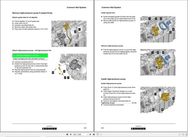
High-pressure pump remove, install
Additional work
High-pressure pump dismantle, assemble
Additional work
Technical data
Important information
Special tools
Dismantle high-pressure pump
Remove metering unit
Remove fuel pump
Remove overflow and flow control valve
Assemble high-pressure pump
Install overflow and flow control valve
Install fuel pump
Install metering unit
High-pressure pump drive remove, install
Additional work
High-pressure pump drive dismantle, assemble
Additional work
Technical data
Important information
Dismantle high-pressure pump drive
Remove drive shaft
Remove drive gear
Unscrew plug screw
Assemble high-pressure pump drive
Screw in locking screw
Install drive gear
Install drive shaft
Flame start system remove, install (variant A, B and D)
Technical data
Remove solenoid valve
Install flame start system
Mount solenoid valve
Mount flame glow plug
Flame start system remove, install (variant C)
Technical data
Remove solenoid valve
Install flame start system
Mount solenoid valve
Mount flame glow plug
Turbocharging
Charge-air manifold remove, install (variant A, B and D)
Additional work
Charge-air manifold remove, install (variant C)
Additional work
Exhaust turbocharger remove, install (variant A, B and C)
Technical data
Exhaust turbocharger remove, install (variant D)
Technical data
Exhaust system
Exhaust manifold remove, install
Additional work
Cylinder head
Rocker arm mechanism remove, install
Additional work
Dismantle and assemble rocker arm mechanism
Additional work
Cylinder head remove, install
Additional work
Valve clearance check, adjust
Important information
Valve stem seals, remove, install
Additional work
Mount cylinder head cover
Valve drive
Camshaft/camshaft bearing remove, installation
Additional work
Check camshaft
Check camshaft radial play
Remove camshaft
Check camshaft bearings
Related Products
-
Liebherr Crane HS HSG Operating Manual Spare Parts List Technical Information PDF DVD
Original price was: 1,500.540Current price is: 540. USDLiebherr Crane HS HSG Operating Manual Spare Parts Catalogue Technical Information DVD Size: 2.17 GB Fomat: PDF Language: EN,DE Brand: Liebherr Type of machine: Liebherr Crawler Crane Window: All Win 32 and 64 Bit, Mac OS Type of document: Liebherr Crane HS Operating Manual Liebherr Crane HS Spare Parts Catalogue Liebherr Crane HS Technical information Liebherr Crane HS Electrical Circuit Diagram Liebherr Crane HS Hydraulic Circuit DiagramHot-64%
REALEASE :
04.07.2022
REALEASE :
04.07.2022
-
Liebherr Mobile Crawler Cranes PDF Spare Parts List DVD
Original price was: 200.140Current price is: 140. USDLiebherr Mobile & Crawler Cranes 1.24 GB PDF Spare Parts Catalog DVDSize: 1.24 GBFormat: PDF, winrarBrand: LiebherrLanguages: English, Deutsch, Spanish, Russian, French, PortugueseType of Machine: Mobile Crane, Crawler Crane, Rough Terrain Crane, Tower CraneType of Document: Spare Parts CatalogsNumber of DVD: 1 DVDOS: Windows Vista, XP, 7, 8.1, 8, 10, MacOSHigh-Speed DownloadDETAIL CONTENTS: “CLICK HERE“Hot-30%
REALEASE :
29.03.2022
REALEASE :
29.03.2022
-
LIEBHERR LTM 1095-5.1 95 Ton Operator Manual Diagnostics LICCON Wiring Schematic PDF
Original price was: 200.60Current price is: 60. USDLIEBHERR LTM 1095-5.1 95 Ton Operator Manual, Diagnostics LICCON & Wiring DiagramSize: 77.3 MBFormat: PDFlanguage: EnglishBrand: LiebherrType of machine: Mobile CraneType of document:Model: LIEBHERR LTM 1095-5.1DETAIL CONTENTS: “CLICK HERE“Hot-70%
REALEASE :
25.03.2022
REALEASE :
25.03.2022
-
Liebherr Crawler Crane with Telescopic Boom LTR 1100 100 Ton Operator Manual Diagnostics LICCON Wiring Diagram
Original price was: 400.160Current price is: 160. USDLiebherr Crawler Crane with Telescopic Boom LTR 1100 100 Ton Operator Manual, Diagnostics LICCON & Wiring Diagram Size: 734 Mb Language: English_EN Format: PDF Model: LTR 1100 Capacity: 100 Ton SN: Z97542 Diesel Engine: D944 A7 DETAIL CONTENTS: “CLICK HERE“Hot-60%
REALEASE :
23.03.2022
REALEASE :
23.03.2022
-
Liebherr Wheeled and Crawler Excavators Updated 03.2022 Service Manuals DVD PDF
Original price was: 800.340Current price is: 340. USDLiebherr Wheeled and Crawler Excavators 48.3GB Updated 03.2022 Service Manuals DVD PDFSize: 48.3 GB (PDF Files)Format: PDFLanguage: EN, DEBrand: LiebherrDate Updated: 03.2022OS: All Windows 32 & 64bitType of Vehicle: Wheeled and Crawler ExcavatorsType of Document: Service ManualsHigh-Speed Link Download DETAIL CONTENTS: “CLICK HERE“Hot-58%
REALEASE :
02.03.2022
REALEASE :
02.03.2022
-
Liebherr Wheel Loader Updated 03.2022 Full Service Manuals DVD PDF
Original price was: 700.340Current price is: 340. USDLiebherr Wheel Loader 24.29GB Updated 03.2022 Full Service Manuals DVD PDFSize: 24.29 GB (PDF Files)Type of Vehicle: Wheel LoadersType of Document: Service ManualsFormat: PDFLanguage: EN, ZH, DEBrand: LiebherrDate Updated: 03.2022OS: All Windows 32 & 64 bitHigh-Speed Link DownloadDETAIL CONTENTS: “CLICK HERE“Hot-51%
REALEASE :
02.03.2022
REALEASE :
02.03.2022
-
Liebherr Crane LTM 1800 Service Manual Operators Manual Schematic
Original price was: 300.180Current price is: 180. USDThey are PDF Service Manual Operators Manual Schematic Manual, You need to use these to repair your vehicle.Hot-40%
REALEASE :
16.09.2022
REALEASE :
16.09.2022
-
Liebherr Mining Excavators 84.88Gb PDF Updated 01.2022 Service Manuals DVD
USDLiebherr Mining Excavators 84.88Gb PDF Updated 01.2022 Service Manuals DVDSize: 84.88 Gb (PDF Files)Type of vehicle: Mining ExcavatorsType of manual: Service ManualLanguage: EnglishBrand: LiebherrFormat: PDFUpdate: 01.2022OS: All WindowsAmount of DVD: 1 DVDREALEASE :
01.13.2022
