
0 ITEMSVIEW CART


✓
Expert Support
✓
Full Speed
✓
100% Working
Liebherr Engine D934 A6 D936 A6 Workshop Manual 10116428
Size: 11.00 MB
Format: PDF
Language: English
Brand: Liebherr
Type of Machine: Engine
Type of Manual: Workshop Manual
Model: Liebherr D934 A6, D936 A6 Engine
Part Number: 10116428
Number of Pages: 298 Pages
20 USD
- Description
Description
Contents:
1 General information
1.1 Structure of this manual
1.2 Important notes within this manual
1.3 Symbols in this manual
1.4 Notes on safety
1.5 Technical Data
1.6 Representations of the engine and engine components
1.7 Diagram of the fuel system
1.8 Diagram of lube oil system
1.9 Diagram of coolant system
1.10 Allocation of ducts in the crankcase and in the cylinder head
1.11 Tools
2 Cylinder head, engine control and valves
2.1 Installing and dismantling the rocker arm support and push rods
2.2 Installing and dismantling the valve fitting (for engines with and without ZBS)
2.3 Installing and dismantling the cylinder head
2.4 Installing and dismantling valve stem seals, valve springs and valves
2.5 Installing and dismantling the roller tappet (valve control)
2.6 Dismantling and installing the camshafts
3 Engine
3.1 Checking combustion pressure
3.2 Installing and dismantling the piston with connecting rod and piston rings
3.3 Installing and dismantling the cylinder liner
3.4 Checking excess length of the cylinder liners
3.5 Installing and dismantling the generator mount
3.6 Installing and dismantling the air-conditioning compressor and generator mount
3.7 Installing and dismantling crankshaft accessories
3.8 Installing and dismantling the front crankshaft seal
3.9 Installing and dismantling the aggregate carrier
3.10 Installing and dismantling the flywheel
3.11 Installing and dismantling the rear crankshaft seal
3.12 Dismantling and installing the flywheel housing
3.13 Dismantling and installing the idler
3.14 Installing and dismantling the crankshaft
3.15 Installing and dismantling the crankshaft gear wheel
4 Fuel system and injection system
4.1 Notes regarding working on the fuel system and injection system
4.2 Installing and dismantling fuel lines
4.3 Installing and dismantling the fuel prefilter with bracket
4.4 Installing and dismantling the fuel fine filter with bracket
4.5 Installing and dismantling the fuel multiplier
4.6 Installing and dismantling the fuel delivery pump
4.7 Installing and dismantling the injection lines
4.8 Installing and dismantling the pressure pipe tube and injection nozzle
4.9 Checking, dismantling and reassembling the injection nozzle (step-type holder)
4.10 Draining the fuel ducts in the crankcase
4.11 Installing and dismantling the injection pump and roller tappet
5 Belt drive
5.1 Installing and dismantling the ribbed V-belt tensioning device
5.2 Installing and dismantling the ribbed V-belt deflection pulley
6 Charge air and exhaust system
6.1 Installing and dismantling the air induction pipe
6.2 Installing and dismantling the connecting line (turbocharger – intercooler)
6.3 Installing and dismantling the exhaust pipes
6.4 Installing and dismantling the engine brake
6.5 Installing and dismantling the intake manifold
6.6 Installing and dismantling the adapter
6.7 Installing and dismantling the exhaust stack
6.8 Installing and dismantling the flange
6.9 Installing and dismantling the thermal protection plate on the exhaust pipe
6.10 Installing and dismantling the thermal protection plate on the turbocharger
6.11 Installing and dismantling the turbocharger
6.12 Checking axial clearance and radial clearance of the turbocharger
7 Electrical system
7.1 Installing and dismantling the heater flange
7.2 Installing and dismantling the generator
7.3 Installing and dismantling the generator belt pulley
7.4 Installing and dismantling the starter
7.5 Installing and dismantling the sensors
7.6 Installing and dismantling the engine control unit
7.7 Installing and dismantling the engine control unit-mount
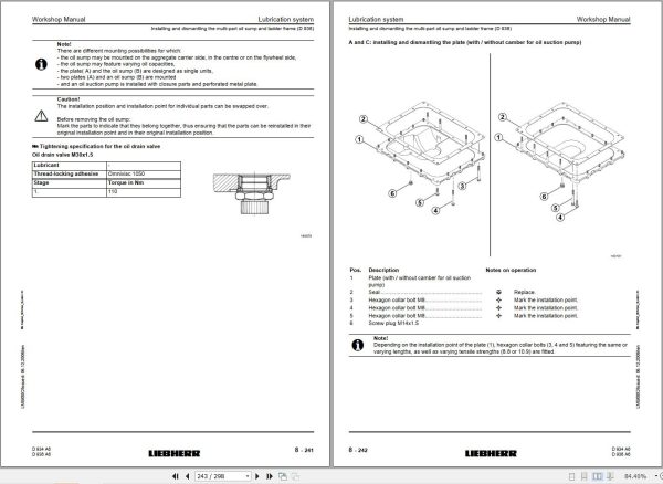
8 Lubrication system
8.1 Installing and dismantling the crankcase breather
8.2 Installing and dismantling the oil return-flow line (crankcase breather)
8.3 Installing and dismantling the oil dipstick and guide tube
8.4 Installing and dismantling the oil intake
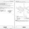
8.5 Installing and dismantling the multi-part oil sump and ladder frame (D 936)
8.6 Installing and dismantling the single-unit oil sump
8.7 Installing and dismantling the connector (oil sump – crankcase) (D 934)
8.8 Installing and dismantling the oil suction pipe (D 936)
8.9 Installing and dismantling the ladder frame
8.10 Installing and dismantling the oil cooler housing with oil cooler
8.11 Dismantling and installing the oil pressure pump
8.12 Installing and dismantling the oil suction pump (D 936)
8.13 Installing and dismantling the piston cooling nozzle
8.14 Dismantling and installing the sealing parts of the oil suction pump
8.15 Installing and dismantling the final regulating valve
8.16 Check the oil pressure, adjust as necessary
9 Cooling system
9.1 Installing and dismantling the coolant vent line
9.2 Installing and dismantling the coolant pump
9.3 Installing and dismantling the coolant manifold (on the thermostat housing or aggregate carrier)
9.4 Installing and dismantling the thermostat housing and thermostat
9.5 Checking the thermostat
10 Power take-off and air / air-conditioning compressor
10.1 Installing and dismantling the power take-off for fuel delivery pump
10.2 Dismantling and removing power take-off 1
10.3 Dismantling and removing power take-off 2
10.4 Dismantling and removing power take-off 3
10.5 Dismantling and removing power take-off 4
10.6 Installing and removing the power take-off on the flywheel housing
10.7 Dismantling and installing the switchable power take-off on the flywheel housing
10.8 Installing and dismantling the air-conditioning compressor
Related Products
-
Liebherr Crane HS HSG Operating Manual Spare Parts List Technical Information PDF DVD
Original price was: 1,500.540Current price is: 540. USDLiebherr Crane HS HSG Operating Manual Spare Parts Catalogue Technical Information DVD Size: 2.17 GB Fomat: PDF Language: EN,DE Brand: Liebherr Type of machine: Liebherr Crawler Crane Window: All Win 32 and 64 Bit, Mac OS Type of document: Liebherr Crane HS Operating Manual Liebherr Crane HS Spare Parts Catalogue Liebherr Crane HS Technical information Liebherr Crane HS Electrical Circuit Diagram Liebherr Crane HS Hydraulic Circuit DiagramHot-64%
REALEASE :
04.07.2022
REALEASE :
04.07.2022
-
Liebherr Crawler Crane with Telescopic Boom LTR 1100 100 Ton Operator Manual Diagnostics LICCON Wiring Diagram
Original price was: 400.160Current price is: 160. USDLiebherr Crawler Crane with Telescopic Boom LTR 1100 100 Ton Operator Manual, Diagnostics LICCON & Wiring Diagram Size: 734 Mb Language: English_EN Format: PDF Model: LTR 1100 Capacity: 100 Ton SN: Z97542 Diesel Engine: D944 A7 DETAIL CONTENTS: “CLICK HERE“Hot-60%
REALEASE :
23.03.2022
REALEASE :
23.03.2022
-
LIEBHERR LTM 1095-5.1 95 Ton Operator Manual Diagnostics LICCON Wiring Schematic PDF
Original price was: 200.60Current price is: 60. USDLIEBHERR LTM 1095-5.1 95 Ton Operator Manual, Diagnostics LICCON & Wiring DiagramSize: 77.3 MBFormat: PDFlanguage: EnglishBrand: LiebherrType of machine: Mobile CraneType of document:Model: LIEBHERR LTM 1095-5.1DETAIL CONTENTS: “CLICK HERE“Hot-70%
REALEASE :
25.03.2022
REALEASE :
25.03.2022
-
Liebherr Crane LTM 1800 Service Manual Operators Manual Schematic
Original price was: 300.180Current price is: 180. USDThey are PDF Service Manual Operators Manual Schematic Manual, You need to use these to repair your vehicle.Hot-40%
REALEASE :
16.09.2022
REALEASE :
16.09.2022
-
Liebherr Mobile Crawler Cranes PDF Spare Parts List DVD
Original price was: 200.140Current price is: 140. USDLiebherr Mobile & Crawler Cranes 1.24 GB PDF Spare Parts Catalog DVDSize: 1.24 GBFormat: PDF, winrarBrand: LiebherrLanguages: English, Deutsch, Spanish, Russian, French, PortugueseType of Machine: Mobile Crane, Crawler Crane, Rough Terrain Crane, Tower CraneType of Document: Spare Parts CatalogsNumber of DVD: 1 DVDOS: Windows Vista, XP, 7, 8.1, 8, 10, MacOSHigh-Speed DownloadDETAIL CONTENTS: “CLICK HERE“Hot-30%
REALEASE :
29.03.2022
REALEASE :
29.03.2022
-
Liebherr Mining Excavators 84.88Gb PDF Updated 01.2022 Service Manuals DVD
USDLiebherr Mining Excavators 84.88Gb PDF Updated 01.2022 Service Manuals DVDSize: 84.88 Gb (PDF Files)Type of vehicle: Mining ExcavatorsType of manual: Service ManualLanguage: EnglishBrand: LiebherrFormat: PDFUpdate: 01.2022OS: All WindowsAmount of DVD: 1 DVDREALEASE :
01.13.2022
-
Liebherr Wheel Loader Updated 03.2022 Full Service Manuals DVD PDF
Original price was: 700.340Current price is: 340. USDLiebherr Wheel Loader 24.29GB Updated 03.2022 Full Service Manuals DVD PDFSize: 24.29 GB (PDF Files)Type of Vehicle: Wheel LoadersType of Document: Service ManualsFormat: PDFLanguage: EN, ZH, DEBrand: LiebherrDate Updated: 03.2022OS: All Windows 32 & 64 bitHigh-Speed Link DownloadDETAIL CONTENTS: “CLICK HERE“Hot-51%
REALEASE :
02.03.2022
REALEASE :
02.03.2022
-
Liebherr Wheeled and Crawler Excavators Updated 03.2022 Service Manuals DVD PDF
Original price was: 800.340Current price is: 340. USDLiebherr Wheeled and Crawler Excavators 48.3GB Updated 03.2022 Service Manuals DVD PDFSize: 48.3 GB (PDF Files)Format: PDFLanguage: EN, DEBrand: LiebherrDate Updated: 03.2022OS: All Windows 32 & 64bitType of Vehicle: Wheeled and Crawler ExcavatorsType of Document: Service ManualsHigh-Speed Link Download DETAIL CONTENTS: “CLICK HERE“Hot-58%
REALEASE :
02.03.2022
REALEASE :
02.03.2022
