
0 ITEMSVIEW CART

✓
Expert Support
✓
Full Speed
✓
100% Working
Liebherr Excavator A 924 Rail 1510 Service Manual 12254864
Size: 151.45 MB
Format: PDF
Language: English
Brand: Liebherr
Type of Machine: Excavator
Type of Manual: Service Manual, Electric and Hydraulic Diagrams
Model: Liebherr A 924 Rail 1510 Excavator
From Serial Number: 110003
Order Number: 12254864
Publication Date: 2023
Number of Pages: 2045 Pages
150 USD
- Description
Description
Contents:
000 Safety
000.1 Warning messages
000.2 Description of staff
000.3 Intended use
000.4 Protective measures for staff
000.5 Protective devices on the machine
000.6 Emergency equipment on the machine
000.7 Safe operation
000.8 Safe work
000.9 Safe maintenance
000.10 Modifications to the machine
010 Introduction
010.008 Component documentation
010.008 Innovations and changes
010.030 Standards and regulations
010.043 Installation instructions: Mounting clamping nuts
010.043 Special tools
010.070 Preservation guidelines
010.071 Conservation of hydraulic cylinders
010.072 Conservation guidelines for the SCR system
020 Technical data
020.001 Technical data
030 Maintenance
030.001 Maintenance
030.001 Adjustment checklist
030.001 Adjustment procedures
040 Drive group
040.011 Technical data, diesel engine
040.021 Diesel engine D924 A7
040.022 Cummins QSB 4.5 diesel engine
040.026 SCR exhaust treatment system
040.027 Exhaust system (Cummins diesel engine)
040.031 Diesel exhaust fluid system
040.036 Fuel system
040.037 Engine fuel system (Cummins diesel engine)
040.041 Air filter system
040.042 Air filter system (Cummins diesel engine)
040.051 SCRF exhaust treatment system
040.060 Coupling
040.062 Cummins coupling
050 Cooling system
050.005 Coolant temperature
050.011 Cooling unit
050.020 Fan drive
050.030 Reversible fan drive
060 Working hydraulics
060.001 Overview of hydraulic symbols
060.002 Colour code of hydraulic schematics
060.003 Depressurising hydraulic system
060.004 Bleeding hydraulic system
060.008 LSC system
060.015 Function of rail guide system Low Rider
060.016 Function of High Rider rail guide system
060.020 Design of uppercarriage hydraulic system
060.032 Design of hydraulic system, undercarriage
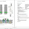
060.033 Hydraulic schematics
070 Travel hydraulics
070.005 Travel hydraulics: overview
070.015 DMVA O 165 travel motor
080 Hydraulic components
080.010 PowerLift additional pressure stage
080.015 Hydraulic tank
080.025 Double variable-displacement pump DPVP O 108
080.040 Servo control unit
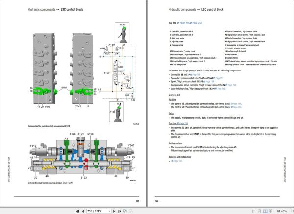
080.051 LSC control block
080.052 High-pressure circuit 1 (HDK1) control axis
080.053 Separating plate
080.054 Control axis / slewing gear
080.055 Medium pressure circuit control axis / turn grapple
080.056 Adjustable boom cylinder control axis
080.057 Pilot control valve 3x
080.058 Pilot control valves
080.059 Leak oil check on control valve blocks
080.070 Control block of rail guide system
080.072 Slewing gear motor
080.075 Rotary connection 13x
080.080 Hydraulic differential cylinder
080.090 Pressure accumulator
080.100 Line break safety valves
080.105 Line break safety valve on the stick cylinder
090 Steering system
090.010 Hydraulic steering system
100 Brake system
100.010 Hydraulic brake system with rail wheel brake
100.020 Compact brake block
100.020 Track wheel brake
100.050 Compressed air system
100.060 Pneumatic single-circuit wagon brake system
100.070 Pneumatic dual-circuit wagon brake system
100.080 Hydraulic dual-circuit wagon brake system
110 Electrical system
110.001 Overview of electrical symbols
110.002 Circuit diagrams in LIDOS
110.005 Overview of ground connections
110.011 Rail-road control unit
110.020 Electrical system: operator’s platform, wheeled
110.030 Electrical system: uppercarriage
110.034 Electrical system: Fuses and relays
110.040 Electrical system: undercarriage
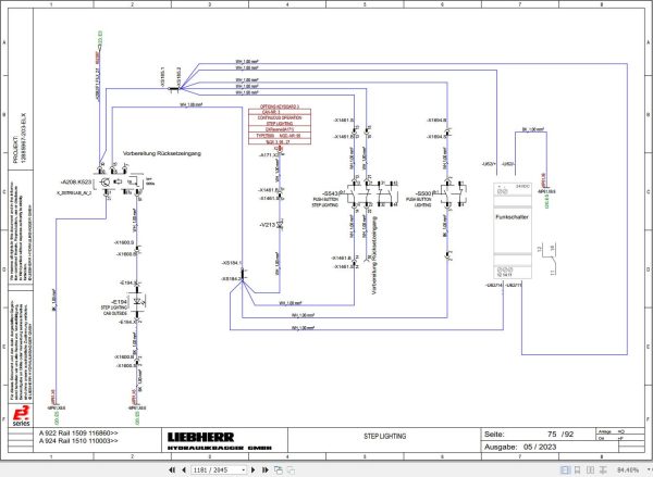
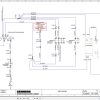
110.050 Electrical schematic
110.10 Electrical schematic: Cummins QSB diesel engine
110.096 Resistance measurement
110.200 Pilot control unit / joystick
120 Transmission/travel gearbox
.010 Achsverteilergetriebe 2 HL 270 / 290
120.022 Pilot control valve for transmission
130 Axles/travel gear
130.001 Tyres
130.003 Checking oscillating axle bearing for wear
130.005 Oscillating axle support
130.025 Oscillating axle MS-E 3070
130.026 Rigid axle MT-E 3070
130.050 Rail guide system with track wheel brake
130.100 Rail guide axle: wear measurement
140 Steel parts of the basic machine
140.010 Repair welding guideline
150 Working attachment
150.010 Removing and installing the working attachment
150.015 Height and laterally adjustable boom
150.040 Hydraulic quick coupler
150.042 Third-party quick coupler interface
150.060 Electrical changeover between bucket and grapple operation
150.061 Manual changeover of bucket to grapple
150.062 Height limiting
150.064 Slew limitation
150.066 Load moment limitation
160 Operator’s cab, heating and air conditioning
160.021 Auxiliary heater
160.035 Heating and air conditioning unit
160.041 Air conditioning
160.045 Diagnosis and maintenance of the air conditioning system
170 Lubrication system
170.001 Repair of lubrication hose
170.005 Automatic central lubrication system
170.015 Central lubrication pump
170.025 Progressive distributor
180 Slewing gearbox and slewing ring
180.020 Slewing gearbox
180.030 Slewing brake
180.032 Positioning slewing brake
180.050 Slewing ring
190 Equipment and options
190.001 LiDAT remote diagnosis system
190.002 LiDAT: checking connection status
190.004 LiDAT remote diagnosis system (LiTU03)
190.005 LiDAT: Creating a report and snapshot
190.007 SOLIDLINK hydraulic coupling system
190.008 Test template for Solidlink
190.010 Tool control
190.014 Tool Management
190.022 Operator identification
190.041 Tiltrotator TR-20/TR-25
190.050 Refuelling system
190.053 Hydraulic connections on the stick
190.055 Bypass filter
190.060 Control unit for pre-heating
190.062 Hydraulic oil pre-heating
190.066 Coolant pre-heating
190.070 Backward stability
190.080 Trailer socket
190.090 Camera monitoring system
200 Diagnosis
200.005 Sculi variables editor
200.006 Sculi access to the variables
200.010 Testing and adjustment software wizard
200.012 Accelerating starting time from Sculi Wizard
200.035 CAN module addressing
200.090 Malfunctions
200.095 Information menu
200.098 Master module 5: master module (central control unit)
200.100 Master module 5: Reset to factory settings
200.102 Master module 5: Connect “Lift†function
200.104 Master module 5: software update
200.106 Master module 5: Connecting SCULi diagnostic software
200.108 Master module 5: Service file
200.110 Master module 5: import license file
200.112 Master module 5: software backup
200.114 Master module 5: event data backup
200.130 Editing machine variables locally on the machine with SCULi
200.140 Editing machine variables on the machine using SCULi Teleservice
200.150 Editing machine variables locally on the machine with LiDIAG
200.160 Editing machine variables via LiDIAG Teleservice
Related Products
-
Liebherr Mining Excavators 84.88Gb PDF Updated 01.2022 Service Manuals DVD
USDLiebherr Mining Excavators 84.88Gb PDF Updated 01.2022 Service Manuals DVDSize: 84.88 Gb (PDF Files)Type of vehicle: Mining ExcavatorsType of manual: Service ManualLanguage: EnglishBrand: LiebherrFormat: PDFUpdate: 01.2022OS: All WindowsAmount of DVD: 1 DVDREALEASE :
01.13.2022
-
Liebherr Mobile Crawler Cranes PDF Spare Parts List DVD
Original price was: 200.140Current price is: 140. USDLiebherr Mobile & Crawler Cranes 1.24 GB PDF Spare Parts Catalog DVDSize: 1.24 GBFormat: PDF, winrarBrand: LiebherrLanguages: English, Deutsch, Spanish, Russian, French, PortugueseType of Machine: Mobile Crane, Crawler Crane, Rough Terrain Crane, Tower CraneType of Document: Spare Parts CatalogsNumber of DVD: 1 DVDOS: Windows Vista, XP, 7, 8.1, 8, 10, MacOSHigh-Speed DownloadDETAIL CONTENTS: “CLICK HERE“Hot-30%
REALEASE :
29.03.2022
REALEASE :
29.03.2022
-
Liebherr Crane HS HSG Operating Manual Spare Parts List Technical Information PDF DVD
Original price was: 1,500.540Current price is: 540. USDLiebherr Crane HS HSG Operating Manual Spare Parts Catalogue Technical Information DVD Size: 2.17 GB Fomat: PDF Language: EN,DE Brand: Liebherr Type of machine: Liebherr Crawler Crane Window: All Win 32 and 64 Bit, Mac OS Type of document: Liebherr Crane HS Operating Manual Liebherr Crane HS Spare Parts Catalogue Liebherr Crane HS Technical information Liebherr Crane HS Electrical Circuit Diagram Liebherr Crane HS Hydraulic Circuit DiagramHot-64%
REALEASE :
04.07.2022
REALEASE :
04.07.2022
-
Liebherr Crawler Crane with Telescopic Boom LTR 1100 100 Ton Operator Manual Diagnostics LICCON Wiring Diagram
Original price was: 400.160Current price is: 160. USDLiebherr Crawler Crane with Telescopic Boom LTR 1100 100 Ton Operator Manual, Diagnostics LICCON & Wiring Diagram Size: 734 Mb Language: English_EN Format: PDF Model: LTR 1100 Capacity: 100 Ton SN: Z97542 Diesel Engine: D944 A7 DETAIL CONTENTS: “CLICK HERE“Hot-60%
REALEASE :
23.03.2022
REALEASE :
23.03.2022
-
Liebherr Wheel Loader Updated 03.2022 Full Service Manuals DVD PDF
Original price was: 700.340Current price is: 340. USDLiebherr Wheel Loader 24.29GB Updated 03.2022 Full Service Manuals DVD PDFSize: 24.29 GB (PDF Files)Type of Vehicle: Wheel LoadersType of Document: Service ManualsFormat: PDFLanguage: EN, ZH, DEBrand: LiebherrDate Updated: 03.2022OS: All Windows 32 & 64 bitHigh-Speed Link DownloadDETAIL CONTENTS: “CLICK HERE“Hot-51%
REALEASE :
02.03.2022
REALEASE :
02.03.2022
-
LIEBHERR LTM 1095-5.1 95 Ton Operator Manual Diagnostics LICCON Wiring Schematic PDF
Original price was: 200.60Current price is: 60. USDLIEBHERR LTM 1095-5.1 95 Ton Operator Manual, Diagnostics LICCON & Wiring DiagramSize: 77.3 MBFormat: PDFlanguage: EnglishBrand: LiebherrType of machine: Mobile CraneType of document:Model: LIEBHERR LTM 1095-5.1DETAIL CONTENTS: “CLICK HERE“Hot-70%
REALEASE :
25.03.2022
REALEASE :
25.03.2022
-
Liebherr Crane LTM 1800 Service Manual Operators Manual Schematic
Original price was: 300.180Current price is: 180. USDThey are PDF Service Manual Operators Manual Schematic Manual, You need to use these to repair your vehicle.Hot-40%
REALEASE :
16.09.2022
REALEASE :
16.09.2022
-
Liebherr Wheeled and Crawler Excavators Updated 03.2022 Service Manuals DVD PDF
Original price was: 800.340Current price is: 340. USDLiebherr Wheeled and Crawler Excavators 48.3GB Updated 03.2022 Service Manuals DVD PDFSize: 48.3 GB (PDF Files)Format: PDFLanguage: EN, DEBrand: LiebherrDate Updated: 03.2022OS: All Windows 32 & 64bitType of Vehicle: Wheeled and Crawler ExcavatorsType of Document: Service ManualsHigh-Speed Link Download DETAIL CONTENTS: “CLICK HERE“Hot-58%
REALEASE :
02.03.2022
REALEASE :
02.03.2022
