
0 ITEMSVIEW CART

✓
Expert Support
✓
Full Speed
✓
100% Working
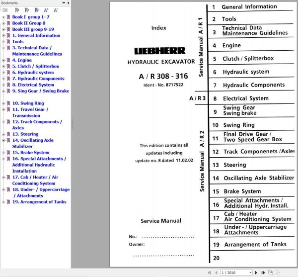
Liebherr Excavator A308 to A316 Service Manual 8717522
Size: 150.21 MB
Format: PDF
Language: English
Brand: Liebherr
Type of Machine: Excavator
Type of Manual: Service Manual, Electric and Hydraulic Diagrams
Model: Liebherr A 308, R 308, A 310, A 310 B, R 310, R 310 B, A 312, R 312, A 316
Engine: BF4M1011F, BF4M2011, BF4L1011LK46, BF4M1012E, BF4M1013E (Tier 2 – Stage II and before)
Order Number: 8717522
Number of Pages: 2010 Pages
100 USD
- Description
Description
Contents:
1. General Information
1.10 Safety Guidelines
1.20 Charts / Norms
1.50 Service Fluids
1.55 Oil Specification Chart “LS-Oil”
2.Tools
2.01 Listing of special tools for excavators (general)
2.03 Listing of special tools for Deutz Engine
2.05 Listing of special tools for hydraulic system
2.06 Listing of special tools for electrical connectors
2.07 Listing of special tools for gears
2.08 Listing of special tools for axles
2.10 Listing of special tools for Piston Wrech
2.11 Listing of special tools for Special assy spanner
2.12 Listing of special tools for Removal device
2.13 Listing of special tools for Ring nut spanner
2.14 Listing of special tools for Spool travel measuring tool
2.15 Listing of special tools for Testing device
2.16 Listing of special tools for Push out and centering pin
2.17 Listing of special tools for Intermiate plate
3. Technical Data / Maintenance Guidelines
3.08 Technical Data A 308 from 101
3.09 Technical Data R 308 from 101
3.10 Technical Data A 310 from 101
3.11 Technical Data A 310 B from 1001
3.12 Technical Data R 310 from 101
3.13 Technical Data R 310 B from 1001
3.14 Technical Data A 312 from 101
3.16 Technical Data R 312 from 101
3.17 Technical Data A 316 from 101
3.18 Maintenance Guidelines A 308 from 101
3.19 Maintenance Guidelines R 308 from 101
3.20 Maintenance Guidelines A 310 from 101
3.21 Maintenance Guidelines A 310 B from 1001
3.22 Maintenance Guidelines R 310 from 101
3.23 Maintenance Guidelines R 310 B from 1001
3.24 Maintenance Guidelines A 312 from 101
3.26 Maintenance Guidelines R 312 from 101
3.28 Maintenance Guidelines A 316 from 101
4. Engine
4.08 Engine BF 4 M 1011 F A/R 308 from 101
4.09 Engine BF 4 M 2011 A 308 from 12009 / R 308 from 12069
4.10 Engine BF 4 L 1011 A/R 310 from 101
4.12 Engine BF 4 M 1012 E A/R 310 B from 1001 / A/R 312 from 101
4.14 Engine BF 4 M 1013 E A 316 from 101
5. Clutch / Splitterbox
5.05 Elastic Coupling A/R 308 / A/R 310 / A/R 312 from 101 / A/R 310 B 1001
5.10 Elastic Coupling A 312 from 861 / R 312 from 257 / A 316 from 101
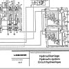
6. Hydraulic system
6.08 Hydraulic System Pressure Settings and Flow A 308 from 101
6.09 Hydraulic System Pressure Settings and Flow R 308 from 101
6.10 Hydraulic System Pressure Settings and Flow A 310 from 101 / A 310 B from 1001
6.11 Hydraulic System Pressure Settings and Flow R 310 from 101 / R 310 B from 1001
6.12.01 Hydraulic System Pressure Settings and Flow A 312 from 101
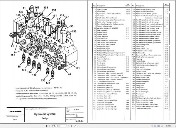
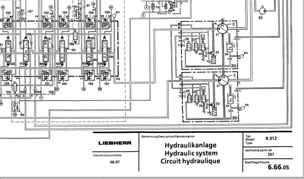
6.12.05 Hydraulic System Pressure Settings and Flow R 312 from 101
6.13 Hydraulic System Pressure Settings and Flow A 316 from 101
6.14 Adjustment Procedure A/R 308 from 101
6.15 Adjustment Procedure A/R 310 from 101
6.16 Adjustment Procedure A/R 310 B from 1001
6.17 Adjustment Procedure A/R 312 from 101
6.18 Adjustment Procedure A 312 from 861
6.19 Adjustment Procedure A 316 from 101
6.20 Hydraulic System – High and Low Pressure Circuit A 308 from 101 / A 310 B from 1001
6.25 Hydraulic System – High and Low Pressure Circuit R 308 from 101 / R 310 B from 1001
6.30 Hydraulic System – High Pressure Circuit A 310 from 101
6.35 Hydraulic System – Low Pressure Circuit A 310 from 101
6.40 Hydraulic System – High Pressure Circuit R 310 from 101
6.45 Hydraulic System – Low Pressure Circuit R 310 from 101
6.60 Hydraulic System A 312 from 101
6.61 Hydraulic System A 312 from 861
6.65 Hydraulic System R 312 from 101
6.66 Hydraulic System R 312 from 257
6.80 Hydraulic System A 316 from 101
6.81 Hydraulic System A 316 from 206
7. Hydraulic Components
7.10 Variable Displacement Pumps A 10 V “DFLR/DFLR” R 310 from 101
7.12 Variable Displacement Pumps A 10 V “DFSR/DSLR” A 310 from 101
7.14 Variable Displacement Pumps A 10 V “DFSR/DFSR” A/R 308 from 101 / A/R 310 B from 1001 / A/R 312 from 101
7.15 Variable Displacement Pumps A 11 V “LRDC” A 312 from 861 / R 312 from 257 / A 316 from 101
7.16 Pump Flow Diaqgramm A/R 308 from 101
7.17 Pump Flow Diaqgramm A/R 310 from 101
7.18 Pump Flow Diaqgramm A/R 312 from 101
7.19 Pump Flow Diaqgramm A 316 from 101
7.22 Hydraulic Fixed Displacement Motor A 2 FE Travel- and Slewing Gear A/R 308 – A / R 312 from 101
7.23 Hydraulic Fixed Displacement Motor A 2 FE Slewing Gear A 316 from 101
7.26.01 Hydraulic Variable Displacement Motor A 6 VM HA A 308 – A 312 / from 101
7.26.11 Hydraulic Variable Displacement Motor A 6 VM HA A 308 from 271 / A 310 B from 1001 / A 312 from 878 / A 316 from 101
7.27 Hydraulic Variable Displacement Motor A 6 VE HA R 308 – R 312 from 101
7.28 Hydraulic Variable Displacement Motor LMV 100 A 316 from 202
7.29 Hydraulic Variable Displacement Motor DMVA 108 A 312 from 1415
7.30 Hydraulic Cylinder A/R 308 – A 316 from 101
7.35 Hydraulic Cylinder Chart A/R 308 from 101
7.36 Hydraulic Cylinder Chart A/R 310 from 101
7.37 Hydraulic Cylinder Chart A/R 310 B from 1001
7.38 Hydraulic Cylinder Chart A/R 312 from 101
7.39 Hydraulic Cylinder Chart A 316 from 101
7.42 Hydraulic Servo Control A/R 310 from 101
7.43 Hydraulic Servo Control A/R 308 from 101 / A/R 310 B from 1001 / A/R 312 from 101 / A 316 from 101
7.46 Control Oil Unit AQ/R 308 – A 316 from 101
7.50 Servo Control with Joystick Lever A/R 308 – A 316 from 101
7.52 Servo Control with Foot Pedal 2-way (for travel gear) R 308 – R 312 from 101
7.54 Servo Control with Foot Pedal 2-way (for attachment installation) A/R 308 – A 316 from 101
7.55 Servo Control with Foot Pedal 1-way (for travel gear) A 308 – A 316 from 101
7.64 Control Valve Block 7-way NG 16 Commercial A/R 310 from 101
7.66 Control Valve Block 8-way NG 16 Rexroth A 308 – A 316 from 101
7.68 Control Valve Block 8-way NG 16 Rexroth R 308 from 101 / R 310 B from 1001 / R 312 from 101
7.69 Control Valve Block 8-way NG 16 Rexroth R 308 from 125 / R 310 B from 1030 / R 312 from 257
7.70 Rotary connection 1-way Knorr R 310 from 101
7.71 Rotary connection 1-way Tries R 308 from 101 / R 310 B from 114 / R 312 from 101
7.72 Rotary connection 6-way Tries A 308 – A 316 from 101
7.74 Rotary connection 5- an d 7 way Liebherr A/R 308 – A 316 from 101
7.80 Primary-PR Valve pilot Controlled A/R 310 from 101
7.81 Pilot controlled PR Valve with Pressure Cut in Stage A 316 from 101
7.82 Secondary-PR Valve with Suction Function A/R 310 from 101
7.83 Secondary-PR Valve with Suction Function A/R 308 from 101 / A/R 310 B from 1001 / A/R 312 from 101 / A 316 from 101
7.84 Suction Valve A 310 from 101
7.85 Suction Valve A/R 308 from 101 / A/R 310 B from 1001 / A/R 312 from 101 / A 316 from 101
7.86 Pressure Relief Valve, direct controlled A 310 from 101
7.88 Restrictor Check Valve A/R 308 – A 316 from 101
7.90 Distributor Valve A 310 from 101
7.91 Check Valve with hydraul. Release A 308 – A 316 from 101
7.92 Dual Check Valve with hydraul. Release A 308 – A 316 from 101
7.94 Travel Brake Valve A 308 – A 316 from 101
7.96 Load Holding Valve A/R 308 – A 316 from 101
7.97 Brake Valve R 308 from 101 / R 310 B from 1001 / R 312 from 101
7.98 Brake Valves for Swing Motor A/R 308 – 312 from 101
8. Electrical System
8
.08 Components of the Electricsystem A 308 / from 101
8.09 Components of the Electric system A 308 / from 454
8.10 Components of the Electric system A 310 / from 101
8.11.01 Components of the Electric system A 310 B / from 1001
8.11.10 Components of the Electric system A 310 B
/ from 1298
8.12 Components of the Electric system A 312 /
from 101
8.13 Components of the Electric system A 312 / from 1107
8.14 Components of the Electric system A 316 /
f rom 101
8.15 Components of the Electric system A 316 / from 331
8.18 Components of the Electric system R 308 /
from 101
8.19 Components of the Electric system R 308 / from 161
8.20 Components of the Electric system R
310 / from 101
8.21.01 Components of the Electric system R 310 B / from 100
1
8.21.10 Components of the Electric system R 310 B / from 1038
8.22 Components of the Electric system R 312 / from 101
8.23 Components of the Electric system R 312 / from 322
8.30 Electric System Basic Machine A 308 / from 101
8.31 Electric System Basic Machine A 308 / from 454
8.35 Electric System Basic Machine R 308 / f
rom 101
8.36 Electric System Basic Machine R 308 / from 161
8.40 Electric System Basic Machine A 310 / from 101
8.42 Electric System Basic Machine A 310 B / from 1001
8.43 Electric System Basic Machine A 310 / from 1298
8.45 Electric System Basic Machine R 310 / from 101
8.47 Electric System Basic Machine R 310 B / from 1001
8.48 Electric System Basic Machine R 310 B / from 1038
8.50 Electric System Basic Machine A 312 /
from 101
8.51 Electric System Basic Machine A 312 / from 900
8.52 Electric System Basic Machine A 312 / from 1107
8.55 Electric System Basic Machine R 312 / from 101
8.56 Electric System Basic Machine R 312 / from 322
8.57 Electric System Basic Machine A316
/ from 101
8.58 Electric System Basic Machine A 316 / from 206
8.59 Electric System Basic Machine A 316 / from 331
8.60 Electric System Installations Kits A 308 – A 316 / frim 101
8.70 Slip Ring Rotary Connection A 308 – A 316 / from 101
9. Sing Gear / Swing Brake
9.10 Swing Gear – Trasmital A/R 310 from 101
9.12 Swing Gear – Trasmital A/R 308 from 101 / A 310 from 206 / R 310 from 111 / A/R 310 B from 1001 / A/R 312 from 101
9.14 Swing Gear – Trasmital A 316 from 101
9.18 Swing Brake A/R 308 / A 316 from 101 / A/R 310 B from 1001
9.20 Swing Brake A/R 310 / A/R 312 from 101
10. Swing Ring
10.10 Swing Ring A/R 308 / A/R 310 / A/R 312 / A 316 from 101 / A/R 310 B from 1001
11. Travel Gear / Transmission
11.10 Travel Gear Trasmital R 308 from 101 / R 310 from 101
11.15 Travel Gear Trasmital R 310 B from 1001 / R 312 from 101
11.20 Travel Brake R 310 from 101 / R 312 from 101
11.25 Lifetime Seal R 308 – R 312 from 101
11.28 Transmission Hurth 353 2-gear A 308 from 101
11.30 Transmission Hurth 353 1-gear A 310 from 101
11.32 Transmission Hurth 355 2-gear A 310 B from 1001
11.35 Transmission ZF 2 HL 100 2-gear A 312 from 101
11.36 Transmission ZF 2 HL 70 2-gear A 312 from 766
11.38 Transmission NAF VGL 350 2-gear A 316 from 101
11.40 Transmission ZF 2 HL 70 2-gear A 316 from 206
11.50 Gear shifting unit HBGV – Valve Block A 312 from 101
12. Track Components / Axles
12.02 Technical Data R 308 from 101
12.03 Technical Data R 310 from 101
12.04 Technical Data R 312 from 101
12.06 Wear of Track Components R308 – R312 from 101
12.09 Wear Limits of Track Components R 308 – R 312 from 101
12.12 Track Components R 308 – R 312 from 101
12.15 Slipring Seal R 308 – R 312 from 101
12.26 Idler R 308 – R 310 from 101
12.28 Idler R 312 from 101
12.31 Tension Unit R 308 – R 310 from 101
12.33 Tension Unit R 312 from 101
12.41 Track Roller R 308 – R 312 from 101
12.46 Carrier Roller R 308 – R 312 from 101
12.58 Steering Axle with Disk Brake A 308 from 101
12.60 Steering Axle with Disk Brake A 310 from 101 / A 310 B 1001
12.65 Steering Axle with Disk Brake A 312 from 101 / A 316 from 206
12.67 Steering Axle with Disk Brake A 316 from 101
12.68 Steering Axle with Disk Brake A 312 from 1415
12.70 Fixed Axle with Disk Brake A 308/A310 from 101 A 310 B from 1001
12.75 Fixed Axle with Disk Brake A 312 from 101
12.76 Fixed Axle with Drum Brake A 312 from 290 / A 316 from 206
12.77 Fixed Axle with Disk Brake A 316 from 101
12.78 Fixed Axle with Disk Brake A 312 from 1415
12.79 Differantial A 308 from 101
12.80 Differantial A 308/A310 from 101 / A 310 B from 1001
12.85 Differantial A 312 from 101 / A 316 from 206
12.86 Differantial A 312 from 1415
12.87 Differantial A 316 from 101
12.90 Tire Chart A 308 – A 316 from 101
13. Steering
13.10 Hydrostatic Steering System A 308/A 310/A 312/A 316 from 101 / A 310 B from 1001
13.20 Servostat System A 308/A 310/A 312/A 316 from 101 / A 310 B from 1001
13.30 Steering Cylinder A 308/A 310 from 101 A 310 B from 1001
13.32 Steering Cylinder A 308/A 310 from 101 A 310 B from 1001
13.33 Steering Cylinder A 312 from 1415
13.34 Steering Cylinder A 316 from 101
13.50 Four Wheel Steering (Installation A 308 from 101
13.51 Electronic Four Wheel Steering A 308 from 101
13,52 Four Wheel Steering (Installation) A 308 from 454
13.53 Electronic Four Wheel Steering A 308 from 454
14. Oscillating Axle Stabilizer
14.10 Oscillating Axle Stabilizer A 310 from 101
14.12 Oscillating Axle Stabilizer A 308/A 312/A 316 from 101 / A 310 from 695 / A 310 B from 1001
14.20 Stabilizer Cylinder A 310 from 101
14.22 Stabilzer Cylinder A 308/A 312/A 316 from 101 / A 310 from 200 (approx.) / A 310 B from 1001
15. Brake System
15.05 General Data and Operating Pressures A 310 from 101
15.06 General Data and Operating Pressures A 308/A 312/A 316 from 101 / A 310 B from 1001
15.10 Hydraulic Brake System / Operating Brake A 308/A 310/A 312/A 316 from 101 / A 310 B from 1001
15.20 Brake system / Parking Brake A 310 from 101
15.30 Compact Brake Block A 308/A 310/A 312/A 316 from 101 / A 310 B from 1001
16. Special Attachments / Additional Hydraulic Installation
16.03 Overload Warning Device A/R 308 / A 316 from 101 / A/R 310 B from 1001
16,05 Overload Warning Device A/R 310 / A/R 312 from 101
16.08 Load Holding Valve A/R 310 from 101
16.10 Load Holding Valve A/R 308 / A/R 310 from 101 / A/R 310 B from 1001
16.18 Attachment Installation Kit AS1 A/R 308 from 101 / A/R 310 B from 1001
16.20 Attachment Installation Kit AS1/AS2 A/R 310 from 101
16.22 Attachment Installation Kit AS1 A/R 312 / A 316 from 101
16.25 Attachment Installation Kit ASH A/R 310 from 101
16.26 Attachment Installation Kit ASH A/R 308 from 101 / A/R 310 B from 1001
16.27 Attachment Installation Kit ASH A/R 312 from 101
16.30 Attachment Installation Kit AHS1 A/R 310 from 101
16.35 Attachment Installation Kit AHS 11 A/R 308 / A/R 312 / A/R 316 from 101 A/R 310 B from 1001
16.40 Attachment Installation Kit AHS 3 A/R 310 from 101
16.42 Attachment Installation Kit AHS 3 A/R 308 / A/R 312 from 101 / A/R 310 B from 1001
16.45 Attachment Installation Kit AHS 12 A/R 308 / A/R 312 / A/R 316 from 101 / A/R 310 B fom 1001
16.55 Attachment Installation Kit Speeder A 310 from 101
16.57 Attachment Installation Kit Speeder A 312 from 101
16.59 Attachment Installation Kit Variable Displavement Travel Motor A/R 308 / A/R 312 / A/R 316 from 101 / A/R 310 B fom 1001
16.78 Hydraulic Height Adjustable Cab A 316 from 101
16.80 Quick Change Adapter A/R 308 / A/R 310 A/R 312 / A/R 316 from 101 / A/R 310 B fom 1001
16.82 Quik Change Adapter A/R 308 from 03.2002 / A/R 310 B from 03.2002
16.90 Hydraulic Hammer A/R 308 / A/R 312 / A/R 316 from 101 / A/R 310 B fom 1001
17. Cab / Heater / Air Conditioning System
17.50 Heater РAir Conditioning System Made by Q̦lfle Q/R 312 / A 316 from 101
18. Under- / Uppercarriage / Attachments
18.10 Maintenance free Bearings A/R 308 – 316 from 101
18.15 Expander Pin A(R 308 – 316 from 101
18.35 Shut off Installation for Grapple Operation
19. Arrangement of Tanks
19.10 Tank Configuration A/R 310 from 101
19.15 Tank Configuration A/R 312 from 101
Related Products
-
Liebherr Wheel Loader Updated 03.2022 Full Service Manuals DVD PDF
Original price was: 700.340Current price is: 340. USDLiebherr Wheel Loader 24.29GB Updated 03.2022 Full Service Manuals DVD PDFSize: 24.29 GB (PDF Files)Type of Vehicle: Wheel LoadersType of Document: Service ManualsFormat: PDFLanguage: EN, ZH, DEBrand: LiebherrDate Updated: 03.2022OS: All Windows 32 & 64 bitHigh-Speed Link DownloadDETAIL CONTENTS: “CLICK HERE“Hot-51%
REALEASE :
02.03.2022
REALEASE :
02.03.2022
-
LIEBHERR LTM 1095-5.1 95 Ton Operator Manual Diagnostics LICCON Wiring Schematic PDF
Original price was: 200.60Current price is: 60. USDLIEBHERR LTM 1095-5.1 95 Ton Operator Manual, Diagnostics LICCON & Wiring DiagramSize: 77.3 MBFormat: PDFlanguage: EnglishBrand: LiebherrType of machine: Mobile CraneType of document:Model: LIEBHERR LTM 1095-5.1DETAIL CONTENTS: “CLICK HERE“Hot-70%
REALEASE :
25.03.2022
REALEASE :
25.03.2022
-
Liebherr Wheeled and Crawler Excavators Updated 03.2022 Service Manuals DVD PDF
Original price was: 800.340Current price is: 340. USDLiebherr Wheeled and Crawler Excavators 48.3GB Updated 03.2022 Service Manuals DVD PDFSize: 48.3 GB (PDF Files)Format: PDFLanguage: EN, DEBrand: LiebherrDate Updated: 03.2022OS: All Windows 32 & 64bitType of Vehicle: Wheeled and Crawler ExcavatorsType of Document: Service ManualsHigh-Speed Link Download DETAIL CONTENTS: “CLICK HERE“Hot-58%
REALEASE :
02.03.2022
REALEASE :
02.03.2022
-
Liebherr Crawler Crane with Telescopic Boom LTR 1100 100 Ton Operator Manual Diagnostics LICCON Wiring Diagram
Original price was: 400.160Current price is: 160. USDLiebherr Crawler Crane with Telescopic Boom LTR 1100 100 Ton Operator Manual, Diagnostics LICCON & Wiring Diagram Size: 734 Mb Language: English_EN Format: PDF Model: LTR 1100 Capacity: 100 Ton SN: Z97542 Diesel Engine: D944 A7 DETAIL CONTENTS: “CLICK HERE“Hot-60%
REALEASE :
23.03.2022
REALEASE :
23.03.2022
-
Liebherr Crane HS HSG Operating Manual Spare Parts List Technical Information PDF DVD
Original price was: 1,500.540Current price is: 540. USDLiebherr Crane HS HSG Operating Manual Spare Parts Catalogue Technical Information DVD Size: 2.17 GB Fomat: PDF Language: EN,DE Brand: Liebherr Type of machine: Liebherr Crawler Crane Window: All Win 32 and 64 Bit, Mac OS Type of document: Liebherr Crane HS Operating Manual Liebherr Crane HS Spare Parts Catalogue Liebherr Crane HS Technical information Liebherr Crane HS Electrical Circuit Diagram Liebherr Crane HS Hydraulic Circuit DiagramHot-64%
REALEASE :
04.07.2022
REALEASE :
04.07.2022
-
Liebherr Mobile Crawler Cranes PDF Spare Parts List DVD
Original price was: 200.140Current price is: 140. USDLiebherr Mobile & Crawler Cranes 1.24 GB PDF Spare Parts Catalog DVDSize: 1.24 GBFormat: PDF, winrarBrand: LiebherrLanguages: English, Deutsch, Spanish, Russian, French, PortugueseType of Machine: Mobile Crane, Crawler Crane, Rough Terrain Crane, Tower CraneType of Document: Spare Parts CatalogsNumber of DVD: 1 DVDOS: Windows Vista, XP, 7, 8.1, 8, 10, MacOSHigh-Speed DownloadDETAIL CONTENTS: “CLICK HERE“Hot-30%
REALEASE :
29.03.2022
REALEASE :
29.03.2022
-
Liebherr Crane LTM 1800 Service Manual Operators Manual Schematic
Original price was: 300.180Current price is: 180. USDThey are PDF Service Manual Operators Manual Schematic Manual, You need to use these to repair your vehicle.Hot-40%
REALEASE :
16.09.2022
REALEASE :
16.09.2022
-
Liebherr Mining Excavators 84.88Gb PDF Updated 01.2022 Service Manuals DVD
USDLiebherr Mining Excavators 84.88Gb PDF Updated 01.2022 Service Manuals DVDSize: 84.88 Gb (PDF Files)Type of vehicle: Mining ExcavatorsType of manual: Service ManualLanguage: EnglishBrand: LiebherrFormat: PDFUpdate: 01.2022OS: All WindowsAmount of DVD: 1 DVDREALEASE :
01.13.2022
