
0 ITEMSVIEW CART

✓
Expert Support
✓
Full Speed
✓
100% Working
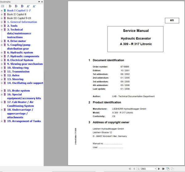
Liebherr Excavator A309 to R317 Litronic Service Manual 8718889
Size: 92.93 MB
Format: PDF
Language: English
Brand: Liebherr
Type of Machine: Excavator
Type of Manual: Service Manual, Electric and Hydraulic Diagrams
Model: Liebherr
A 309 LI 20221-
A 311 LI 20222-
A 312 LI 12363-
R 313 LI 27752-
A 314 LI 2001-
A 316 LI 2001-
A 316 LI-IND 2001-
Engine: BF 4 M 1012, BF 4 M 1013 E,BF 4 M 2012 C ,BF 4 M 1013 EC (Tier 2 – Stage II and before)
Order Number: 8718889
Publication Date: 2008
Number of Pages: 2661 Pages
100 USD
- Description
Description
Contents:
1. General Information
1.02 Modification of series
1.10 Safety instructions
1.20 Tightening torques (WN 4037 I)
1.21 Tightening torquex for screw connections
1.22 Assembly instruction for hydraulic cylinder (WN 4121B)
1.24 Assembly instruction for hydraulic cylinder (WN 4122B)
1.50 Fuels and lubricants
1.55 Lubricant list TE-ML 05
1.56 Lubricant list TE-ML 07
2. Tools
2.01 Special tools general
2.03 Special tools for diesel engines
2.05 Special tools for hydraulic systems
2.06 Special tools for electric systems
2.07 Special tools for gears
2.08 Special tools for axles
2.12 Assembly tools for hydraulic cylinders
2.13 Mounting device for piston rod bearings
2.14 Slotted nut wrench for slewing gear
2.15 Mounting device for slewing gear
2.16 Mounting device for travel gear
3. Technical data/maintenance instructions
3.09 Technical data
3.11 Technical data
3.12 Technical data
3.13 Technical data
3.14 Technical data
3.16 Technical data
3.17 Technical data
3.29 Inspection and maintenance schedule
3.32 Inspection and maintenance schedule
3.38 Inspection and maintenance schedule
4. Drive motor
4.02 Technical data of diesel engines
4.03 Technical data of diesel engines
4.04 Technical data of diesel engines
4.05 Technical data of diesel engines
5. Coupling/pump distribution gear
5.05 Coupling
5.10 Clutch
6. Hydraulic system
6.09 Adjustment protocol A 309 Li 20221-27109
6.09.11 Adjustment protocol A 309 Li 27110-
6.11 Adjustment protocol A 311 Li 20222-27111
6.11.11 Adjustment protocol A 311 Li 27112-
6.12 Adjustment protocol A 312 Li 12363-
6.13 Adjustment protocol R 313 Li 27752-
6.14 Adjustment protocol A 314 Li 2001-
6.16 Adjustment protocol A 316 Li 2001-
6.17 Adjustment protocol R 317 Li 18161-
6.20 LSC system
6.22 Layout of hydraulic system A 309 Li – A 311 Li
6.24 Layout of hydraulic system A 312 Li – A 316 Li
6.27 Layout of hydraulic system R 313 Li – R 317 Li
6.30 Adjustment guidelines for hydraulic system A 3109 Li – A 311 Li
6.34 Adjustment guidelines for hydraulic system A 312 Li – A 316 Li
6.37 Adjustment guidelines for hydraulic system R 317 Li 18161-
6.40 Hydraulic system A 309 Li 20221-23502 / A 311 Li 20222-23506
6.40.11 Hydraulic system A 309 Li 23503-27109 / A 311 Li 23507-27111
6.40.21 Hydraulic system A 309 Li 27110- / A 311 Li 27112-
6.42 Hydraulic system A 312 Li 12363-13288
6.42.13 Hydraulic system A 312 Li 13289-29897
6.42.21 Hydraulic system A 312 Li 29898-
6.43 Hydraulic system R 313 Li 27752-
6.44 Hydraulic system A 314 Li 2001-11146 / A 316 Li 2001-11151
6.44.13 Hydraulic system A 314 Li 11147-13103 / A 316 Li 11152-13104
6.44.21 Hydraulic unit A 314 Li 13104- / A 316 Li 13105-28060
6.44.31 Hydraulic unit A 316 Li 28061-
6.47 Hydraulic unit R 317 Li 18161-21204
6.47.11 Hydraulic unit R 317 Li 21205-
7. Hydraulic components
7.01 Hydraulic pumps – dismantling, installation and initial operation
7.02 Double variable-displacement pump A8VO
7.05 LPV variable displacement pump
7.10 DPVO variable displacement pump R 317 Li
7.15 DPVO variable-displacement pump R 313 Li
7.20 Cooling unit
7.24.1 FMF hydraulic fixed displacement motor
7.24.11 FMF hydraulic fixed displacement motor
7.26 LMV regulating motor
7.27 DMVA regulating motor
7.28 Regulating motor A6VE
7.30 Hydraulic cylinder
7.34 Hydraulic cylinder A 312 Li
7.35 Hydraulic cylinder A 314 Li
7.36 Hydraulic cylinder A 316 Li
7.40 Control oil and regulation unit A 309 Li – A 311 Li
7.42 Control oil and regulation unit A 312 Li – R 317 Li
7.45 Pilot control unit 4 x
7.46.1 Pilot control unit 2 way for travel gear drive
7.46.11 Pilot control unit 4 way for travel gear drive
7.47 Pilot control valve 2 x for installation kir
7.48 Pilot control valve 2 x for support
7.49 Pilot control valve 1 x
7.50 Compact control block A 309 Li
7.60 LSC control block A 312 Li – R 317 Li
7.75 Rotary connection 1 x
7.76 Rotary connection 6 x
7.77 Rotary connection 5 x
7.78 Rotary connection 7 x
7.80 TC valve
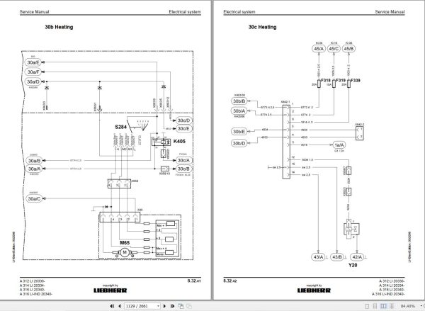
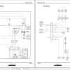
8. Electrical System
8.09 Component arrangement A 309 LI 20221- / A 311 LI 20222-
8.10 Component arrangement A 312 LI 12363- / A 314 LI 2001- / A 316 LI 2001- / A 316 LI-IND 2001-
8.17 Component arrangement R 313 LI 27752- / R 317 LI 18161-
8.20 Electrical system A 309 Li 20221 / A 311 Li 20222-
8.22 Electrical system A 309 Li 29269 / A 311 Li 29270
8.30 Electrical system A 312 Li 12363 / A 312 Li 2001 / A 316 Li 2001
8.32 Electrical system A 312 LI 20330- / A 314 LI 20334- / A 316 Litronic 20340-
8.33 Electrical system A 312 Li 29898- / A 316 Li 28061
8.34 Electrical system A 312 Li 31253- / A 316 Li 31134- / R 317 Li 31140-
8.38 Electrical system R 313 Li / 27752-
8.40 Electrical system R 317 Li 18161-
8.45 Electrical system (Special equipment) A 309 Li – R 317 Li
8.70 Excavator control (Description) A 309 Li – R 317 Li
8.80 Slip ring rotary connection (Description) A 309 Li – R 317 Li
8.100 Electrical system (Special equipment) A 312 Li – A 316 Li
8.101 Blockage 2nd gear
8.102 Function travel left / SF function right
8.103 Travel alarm system
8.104 Blade support front / rear
8.105 Dozer blade with 4-point support
8.106 AHS12 with tool control
8.107 Changeover high – lateral in left handle
8.108 Changeover high – lateral in left handle
8.109 Turning grapple in handle left and right.
8.110 Stroke limitation boom and stick. Bridging button in left handle
8.111 Mower rake
8.112 Auxiliary heating
9. Slewing gear mechanism
9.10 Slewing gear mechanism
9.20 Slewing gear brake
9.24 Slewing gear brake
10. Slewing ring
10.10 Slewing ring
11. Transmission
11.08 2 HL 70 transmission
11.10 2 HL 100 transmission
11.20 2 HL 270 / 290 transmission
11.30 HBGV block for 2 HL 70 / 100
11.32 HBGV block for 2 HL 270 / 290
11.60 Travel gear F40
11.62 FAT 350 travel gear system
11.65 Travel brake R 317 Li 18161-23449
11.67 Travel brake R 313 Li 27752- / R 317 Li 34450-
12. Axles
12.02 Steering axle 212 with multi-disc brake
12.03 Rigid axle 112 with multi-disc brake
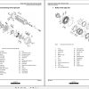
12.05 Differential for the axles 112 / 212 / 162 / 262
12.10 Steering axle 262 LD with multi-disc brake
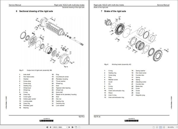
12.11 Rigid axle 162LD with multi-disc brake
12.20 Steering axle
12.21 Rigid axle
12.23 Differential for 162 / 262 axles
12.28 APL – B 745 steering axle with multi-disc brake
12.29 AP – B 745 rigid axle with drum brake
12.30 AP – B 745 rigid axle
12.31 Differential for AP / APL – B 745 axles
12.36 APL – B 755 steering axle with multi-disc brake
12.37 AP – B 755 rigid axle with drum brake
12.39 Differential for AP / APL – B 755 axles
12.41 APL – B 755 HD steering axle with multi-disc brake
12.42 AP – B 755 rigid axle with multi-disc brake
12.44 Differential for AP / APL – B 755 HD axles
12.46 MS – E 3060 steering axle
12.47 MT – E 3060 rigid axle
12.48 MS/MT – E 3060 drive unit and differential
12.54 Tyres and spacer rings
12.60 Chassis / drive
12.62 Technical data / tightening torques
12.64 Technical data / tightening torques
12.66 Wear of chassis parts
12.67 D4L wear limits
12.69 Wear limits – B60
12.72 Chain
12.75 Tensioning unit
12.78 Idler
12.81 Running roller
12.84 Support roller
12.86 Slide ring seal
13. Steering
13.05 Operating pressures of the steering system
13.10 Hydraulic steering system
13.20 Servostat
13.22 Steering valve
13.24 Steering valve
13.32 Steering cylinders
13.34 Steering cylinders
13.50 4-wheel steering
14. Oscillating axle support
14.10 Oscillating axle support with automatic control
14.20 Support cylinders
15. Brake system
15.05 Operating pressures of the brake system
15.10 Hydraulic brake system
15.20 Compact brake block
16. Special equipment/accessory kits
16.04 Pipe fracture safety valve for boom cylinders
16.06 Pipe fracture safety valve for stick cylinder
16.10 Pipe fracture safety valve for regulating cylinder
16.12 Overload warning system
16.16 Hydraulic quick change adapter
16.19 Flow reduction
16.20 Flow reduction
16.24 LIKUFIX Hydraulic Coupling System
16.30 Hydraulic hammers
16.44 Accessory kit AS1
16.48 Accessory kit AHS 1
16.52 Accessory kit AHS 11
16.54 Accessory kit AHS 12
16.56 Accessory kit AHS 12
16.57 Accessory kit AHS 11 / AHS 12 with Tool Control
16.58 Accessory kit AHS 12 with changeover valve
16.60 Individual control
16.62 Kit for control switch-over
16.62 Kit for control switch-over (1)
16.64 Kit for control switch-over
16.66 Dozer blade
16.70 Hydraulic cab elevation system
16.74 Speeder kit
16.86 Generator drive accessory kit
17. Cab Heater / Air Conditioning System
17.30 Heating / air-conditioning system
18. Undercarriage / uppercarriage / attachments
18.15 Passfix bolts
19. Arrangement of Tanks
19.10 Tank arrangement
Related Products
-
Liebherr Wheeled and Crawler Excavators Updated 03.2022 Service Manuals DVD PDF
Original price was: 800.340Current price is: 340. USDLiebherr Wheeled and Crawler Excavators 48.3GB Updated 03.2022 Service Manuals DVD PDFSize: 48.3 GB (PDF Files)Format: PDFLanguage: EN, DEBrand: LiebherrDate Updated: 03.2022OS: All Windows 32 & 64bitType of Vehicle: Wheeled and Crawler ExcavatorsType of Document: Service ManualsHigh-Speed Link Download DETAIL CONTENTS: “CLICK HERE“Hot-58%
REALEASE :
02.03.2022
REALEASE :
02.03.2022
-
Liebherr Crawler Crane with Telescopic Boom LTR 1100 100 Ton Operator Manual Diagnostics LICCON Wiring Diagram
Original price was: 400.160Current price is: 160. USDLiebherr Crawler Crane with Telescopic Boom LTR 1100 100 Ton Operator Manual, Diagnostics LICCON & Wiring Diagram Size: 734 Mb Language: English_EN Format: PDF Model: LTR 1100 Capacity: 100 Ton SN: Z97542 Diesel Engine: D944 A7 DETAIL CONTENTS: “CLICK HERE“Hot-60%
REALEASE :
23.03.2022
REALEASE :
23.03.2022
-
Liebherr Crane HS HSG Operating Manual Spare Parts List Technical Information PDF DVD
Original price was: 1,500.540Current price is: 540. USDLiebherr Crane HS HSG Operating Manual Spare Parts Catalogue Technical Information DVD Size: 2.17 GB Fomat: PDF Language: EN,DE Brand: Liebherr Type of machine: Liebherr Crawler Crane Window: All Win 32 and 64 Bit, Mac OS Type of document: Liebherr Crane HS Operating Manual Liebherr Crane HS Spare Parts Catalogue Liebherr Crane HS Technical information Liebherr Crane HS Electrical Circuit Diagram Liebherr Crane HS Hydraulic Circuit DiagramHot-64%
REALEASE :
04.07.2022
REALEASE :
04.07.2022
-
Liebherr Crane LTM 1800 Service Manual Operators Manual Schematic
Original price was: 300.180Current price is: 180. USDThey are PDF Service Manual Operators Manual Schematic Manual, You need to use these to repair your vehicle.Hot-40%
REALEASE :
16.09.2022
REALEASE :
16.09.2022
-
Liebherr Mobile Crawler Cranes PDF Spare Parts List DVD
Original price was: 200.140Current price is: 140. USDLiebherr Mobile & Crawler Cranes 1.24 GB PDF Spare Parts Catalog DVDSize: 1.24 GBFormat: PDF, winrarBrand: LiebherrLanguages: English, Deutsch, Spanish, Russian, French, PortugueseType of Machine: Mobile Crane, Crawler Crane, Rough Terrain Crane, Tower CraneType of Document: Spare Parts CatalogsNumber of DVD: 1 DVDOS: Windows Vista, XP, 7, 8.1, 8, 10, MacOSHigh-Speed DownloadDETAIL CONTENTS: “CLICK HERE“Hot-30%
REALEASE :
29.03.2022
REALEASE :
29.03.2022
-
Liebherr Mining Excavators 84.88Gb PDF Updated 01.2022 Service Manuals DVD
USDLiebherr Mining Excavators 84.88Gb PDF Updated 01.2022 Service Manuals DVDSize: 84.88 Gb (PDF Files)Type of vehicle: Mining ExcavatorsType of manual: Service ManualLanguage: EnglishBrand: LiebherrFormat: PDFUpdate: 01.2022OS: All WindowsAmount of DVD: 1 DVDREALEASE :
01.13.2022
-
LIEBHERR LTM 1095-5.1 95 Ton Operator Manual Diagnostics LICCON Wiring Schematic PDF
Original price was: 200.60Current price is: 60. USDLIEBHERR LTM 1095-5.1 95 Ton Operator Manual, Diagnostics LICCON & Wiring DiagramSize: 77.3 MBFormat: PDFlanguage: EnglishBrand: LiebherrType of machine: Mobile CraneType of document:Model: LIEBHERR LTM 1095-5.1DETAIL CONTENTS: “CLICK HERE“Hot-70%
REALEASE :
25.03.2022
REALEASE :
25.03.2022
-
Liebherr Wheel Loader Updated 03.2022 Full Service Manuals DVD PDF
Original price was: 700.340Current price is: 340. USDLiebherr Wheel Loader 24.29GB Updated 03.2022 Full Service Manuals DVD PDFSize: 24.29 GB (PDF Files)Type of Vehicle: Wheel LoadersType of Document: Service ManualsFormat: PDFLanguage: EN, ZH, DEBrand: LiebherrDate Updated: 03.2022OS: All Windows 32 & 64 bitHigh-Speed Link DownloadDETAIL CONTENTS: “CLICK HERE“Hot-51%
REALEASE :
02.03.2022
REALEASE :
02.03.2022
