
0 ITEMSVIEW CART


✓
Expert Support
✓
Full Speed
✓
100% Working
Liebherr Excavator A309 to R317 Litronic TCD Service Manual 10449595
Size: 111.19 MB
Format: PDF
Language: English
Brand: Liebherr
Type of Machine: Excavator
Type of Manual: Service Manual, Electric and Hydraulic Diagrams
Model: Liebherr
A 309 LI TCD
A 311 LI TCD
A 312 LI TCD
R 313 LI TCD
A 314 LI TCD
A 316 LI TCD
R 317 LI TCD
Engine: TCD 2012 L04 2V, TCD 2013 L04 2V (Tier 3 – Stage III-A)
Order Number: 10449595
Publication Date: 2011
Number of Pages: 3323 Pages
150 USD
- Description
Description
Contents:
1 General Information
1.02 Changes and modifications to series
1.10 Safety instructions
1.15 Tightening torques for screws in hydraulic flange connections
1.20 Tightening torques (WN 4037 K)
1.21 Tightening torques
1.22 Assembly instruction for hydraulilc cylinder WN 4121 C
1.24 Assembly instruction for hydraulic cylinder WN 4122 B
1.25 Tightening torques for piston rod bearing screws
1.30 Angle-controlled screw tightening
1.35 Hose installation Boom – Stick
1.50 Fuels, lubricants and process chemicals
1.55 TE_ML05 lubricant list
1.56 TE_ML07 lubricant list
1.60 Conservation guidelines
2 Tools
2.01 Special tools – General information
2.02 Special tools for diesel engine TCD 2012
2.03 Special tools for diesel engine TCD 2013
2.05 Special tools for hydraulic unit
2.06 Special tools for electrical equipment
2.07 Special tools for gears
2.08 Special tools for axles
2.12 Assembly tools for hydraulic cylinders
2.13 Mounting device for piston rod bearing
2.14 Slotted nut wrench for slewing gear
2.15 Mounting device for slewing gear
2.16 Mounting device for travel gear
3 Technical data / maintenance instructions
3.09 Technical data A 309 LI TCD
3.11 Technical data A 311 LI TCD
3.12 Technical data A 312 LI TCD
3.13 Technical data R 313 LI TCD
3.14 Technical data A 314 LI TCD
3.16 Technical data A 316 LI TCD
3.17 Technical data R 317 LI TCD
3.21 Inspection and maintenance schedule
3.23 Inspection and maintenance schedule
3.26 Maintenance- and inspection chart
3.43 Adjustment protocol A 309 LI TCD
3.46 Adjustment protocol A 311 LI TCD
3.49 Adjustment protocol A 312 LI TCD
3.52 Adjustment protocol A 314 LI TCD
3.55 Adjustment protocol A 316 LI TCD
3.56 Adjustment protocol A 316 LI Ind TCD
3.58 Adjustment protocol R 313 LI TCD
3.61 Adjustment protocol R 317 LI-TCD
3.62 Adjustment protocol R 317 LI IND TCD
3.75 Adjustment protocol (kits)
3.84 Checking and adjusting tasks
3.85 Checking and adjusting tasks
3.87 Checking and adjusting tasks
3.88 Checking and adjusting tasks
3.100 Maintenance tasks
3.101 Maintenance tasks for diesel engine
3.102 Maintenance tasks for hydraulic system
3.103 Maintenance tasks for electrical system
3.104 Maintenance tasks for slewing gear mechanism
3.105 Maintenance tasks for slewing ring
3.106 Maintenance tasks for transmission
3.107 Maintenance tasks for travel gear mechanism
3.108 Maintenance tasks for axles
3.109 Maintenance tasks for travel gear
3.110 Maintenance tasks for steering system
3.111 Maintenance tasks for oscillating axle support
3.112 Maintenance tasks for brake system
3.113 Maintenance tasks for operator’s cab and heating
3.114 Maintenance tasks for air-conditioning system
3.115 Maintenance tasks for uppercarriage, undercarriage and attachment
3.116 Maintenance tasks for quick-change systems
4 Engine
4.04 Technical data of diesel engines
4.06 Technical data of diesel engines
4.10 Technical data of diesel engines
4.25 Installation and check list
4.30 Liebherr diesel particle filter accessory kit
4.40 Datalogger version 2.3.00
4.41 Datalogger software version 2.3.09
5 Coupling / Splitterbox
5.10 Coupling
6 Hydraulic system
6.10 LSC system
6.20 Design of hydraulic system
6.25 Design of hydraulic system
6.30 Design of hydraulic system
6.40 Hydraulic system
6.52 Hydraulic system
6.54 Hydraulic unit with dozer blade
6.60 Hydraulic system
6.61 Hydraulic system
6.62 Hydraulic system
6.63 Hydraulic system
6.64 Hydraulic system
6.70 Hydraulic system
6.71 Hydraulic system
6.72 Hydraulic system
6.73 Hydraulic system with dozer blade
6.76 Hydraulic system
6.77 Hydraulic system
6.78 Hydraulic system
7 Hydraulic components
7.02 Hydraulic pumps – dismantling, installation and commissioning
7.10 DPVO variable-displacement pump
7.20 Cooling unit
7.24 FMF hydraulic fixed displacement motor
7.25 FMF hydraulic fixed displacement motor
7.26 DMVA regulating motor
7.27 DMVA regulating motor
7.28 Regulating motor A6VE
7.29 Regulating motor A6VE
7.30 Hydraulic cylinder
7.32 Hydraulic double plunger cylinder
7.42 Control oil unit
7.45 Pilot control unit 4 x
7.46 4x pilot control unit for travel drive
7.47 Pilot control unit 2x
7.48 Pilot control valve 2 x
7.56 LSC control valve block
7.58 LSC control block
7.60 LSC control valve block
7.75 Rotary connection 1x
7.76 Rotary connection 6x
7.77 Rotary connection 5x
7.78 Rotary connection 7x
7.80 Double load holding valve
7.82 Support valve / double lowering brake valve
7.86 Double load-holding valve for regulating cylinder
7.95 Accumulator
8 Electrical system
8.01 Overview of electrical symbols
8.02 Notes regarding the electrical system
8.10 Arrangement of components
8.20 Arrangement of components
8.30 Arrangement of components
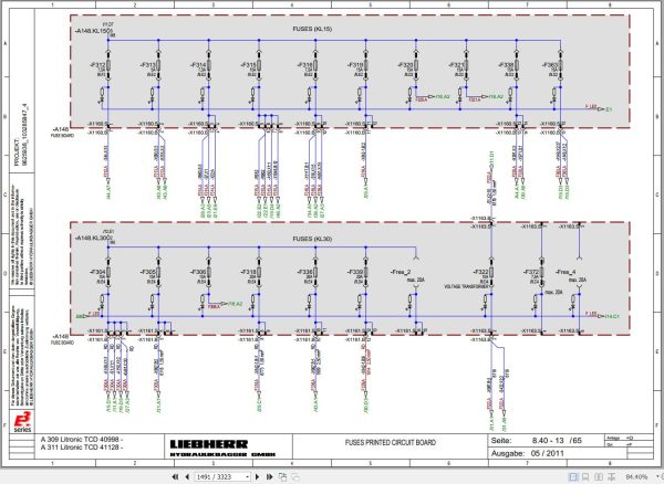
8.40 Electrical system / basic machine
8.50 Electrical system (basic machine)
8.51 Electrical system / basic machine
8.56 Electrical system / basic machine
8.57 Electrical system / basic machine
8.60 Electrical system (basic machine)
8.61 Electrical system / basic machine
8.66 Electrical system / basic machine
8.70 UEC central control system
8.72 UEC central control system
8.74 UEC central control system
8.76 UEC error codes
8.80 Menu control
8.81 Menu control
8.86 Electronic travel drive control
8.90 Slip ring – rotary connection
8.100 Directory of electrical kits
8.101 Control system extension UEC 2
8.102 Control system extension UEC 2
8.103 Particle filter kit
8.104 Stroke limitation with proximity switches
8.105 Dozer blade
8.106 Overload warning system, switchable
8.107 Proportional control
8.108 Rear space camera monitoring system
8.109 Rear space and side camera monitoring system
9 Slewing gear mechanism
9.10 Slewing gear mechanism
9.20 Slewing gear brake
9.24 Slewing gear brake
10 Slewing ring
10.10 Slewing ring
11 Two Speed Gear Box / Travel Gear
11.20 2 HL 270 / 290 transmission
11.32 HBGV block for 2 HL 270 / 290
11.60 FAT 350 travel gear system
11.65 Travel brake
12 Axles / Track Components
12.04 Steering axle 212
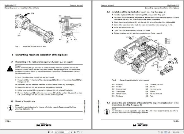
12.06 Rigid axle 112
12.08 Differential for axles 112 / 212
12.12 Steering axle and steered rear axle 262 LD
12.14 Rigid axle 162 LD
12.16 Differential for axles 162 LD/262 LD
12.20 Steering axle 262
12.22 Rigid axle 162
12.24 Differential for 162 / 262 axles
12.30 MS – E 3050 / 3060 steering axle
12.32 MT – E 3050 / 3060 rigid axle
12.34 MS/MT – E 3050 / 3060 drive unit and differential
12.50 Tyres and tyre pressure
12.60 Chassis / drive
12.62 Technical data / tightening torques
12.64 Technical data / tightening torques
12.66 Wear of chassis parts
12.67 D4L wear limits
12.69 Wear limits – B60
12.72 Chain
12.75 Tensioning unit
12.78 Idler
12.81 Running roller
12.82 Idler
12.84 Support roller
12.86 Slide ring seal
13 Steering
13.10 Hydraulic steering system
13.20 Steering valve
13.25 Steering valve
13.32 Steering cylinders
13.35 Steering cylinder
13.50 Four-wheel steering
14 Oscillating axle support
14.10 Oscillating axle support with automatic control
14.20 Support cylinders
15 Brake system
15.05 Operating pressures of the brake system
15.10 Hydraulic brake system
15.20 Compact brake block
16 Special equipment / accessory kits
16.03 Pipe fracture safety valve for boom cylinders
16.04 Pipe fracture safety valve for boom cylinders
16.06 Pipe fracture safety valve for stick cylinder
16.10 Pipe fracture safety valve for regulating cylinder
16.12 Overload warning system
16.14 Switchable overload warning system
16.16 Stroke limitation with proximity switches
16.18 Stroke limitation with angle sensors
16.20 Stroke limitation with angle sensors
16.22 Stick cylinder shut-down with proximity switch
16.32 Hydraulic quick change adapter
16.36 Hydraulic-electric LIKUFIX coupling system
16.42 Accessory kit AS1
16.44 AS 1 proportional control
16.46 Accessory kit AHS 1
16.52 AHS 11 accessory kit with Tool Control
16.53 Changeover of control for AHS 11 with Tool Control
16.54 Accessory kit AHS 11 with Tool Control plus
16.55 Changeover of control for AHS 11 with Tool Control plus
16.56 AHS 11 proportional control
16.60 AHS 12 accessory kit with Tool Control
16.61 Changeover of control for AHS 12 with Tool Control
16.62 Accessory kit AHS 12 with Tool Control plus
16.63 Changeover of control for AHS 12 with Tool Control plus
16.64 AHS 12 proportional control
16.70 Camera monitoring
16.80 Hydraulic cab elevation system
16.81 Hydraulic operator’s cab elevation system
16.84 Bypass filter – RT
16.86 Bypass filter – Liebherr
16.88 Bypass filter- KleenOil
16.90 Reversible fan drive
16.92 Generator drive accessory kit
17 Cab / Heater / Air Conditioning System
17.30 Heating / air-conditioning system
18 Undercarriage / Uppercarriage / Attachments
18.25 Semi-automatic central lubrication system
18.30 Automatic central lubrication system
18.34 Lubricant pump
18.38 SX-E progressive distributor
18.42 MX-F progressive distributor
18.46 Repair instructions for lubrication hoses
19 Tank arrangement
19.10 Tank arrangement
19.20 Tank arrangement
Related Products
-
Liebherr Wheeled and Crawler Excavators Updated 03.2022 Service Manuals DVD PDF
Original price was: 800.340Current price is: 340. USDLiebherr Wheeled and Crawler Excavators 48.3GB Updated 03.2022 Service Manuals DVD PDFSize: 48.3 GB (PDF Files)Format: PDFLanguage: EN, DEBrand: LiebherrDate Updated: 03.2022OS: All Windows 32 & 64bitType of Vehicle: Wheeled and Crawler ExcavatorsType of Document: Service ManualsHigh-Speed Link Download DETAIL CONTENTS: “CLICK HERE“Hot-58%
REALEASE :
02.03.2022
REALEASE :
02.03.2022
-
Liebherr Crane HS HSG Operating Manual Spare Parts List Technical Information PDF DVD
Original price was: 1,500.540Current price is: 540. USDLiebherr Crane HS HSG Operating Manual Spare Parts Catalogue Technical Information DVD Size: 2.17 GB Fomat: PDF Language: EN,DE Brand: Liebherr Type of machine: Liebherr Crawler Crane Window: All Win 32 and 64 Bit, Mac OS Type of document: Liebherr Crane HS Operating Manual Liebherr Crane HS Spare Parts Catalogue Liebherr Crane HS Technical information Liebherr Crane HS Electrical Circuit Diagram Liebherr Crane HS Hydraulic Circuit DiagramHot-64%
REALEASE :
04.07.2022
REALEASE :
04.07.2022
-
Liebherr Mining Excavators 84.88Gb PDF Updated 01.2022 Service Manuals DVD
USDLiebherr Mining Excavators 84.88Gb PDF Updated 01.2022 Service Manuals DVDSize: 84.88 Gb (PDF Files)Type of vehicle: Mining ExcavatorsType of manual: Service ManualLanguage: EnglishBrand: LiebherrFormat: PDFUpdate: 01.2022OS: All WindowsAmount of DVD: 1 DVDREALEASE :
01.13.2022
-
Liebherr Crawler Crane with Telescopic Boom LTR 1100 100 Ton Operator Manual Diagnostics LICCON Wiring Diagram
Original price was: 400.160Current price is: 160. USDLiebherr Crawler Crane with Telescopic Boom LTR 1100 100 Ton Operator Manual, Diagnostics LICCON & Wiring Diagram Size: 734 Mb Language: English_EN Format: PDF Model: LTR 1100 Capacity: 100 Ton SN: Z97542 Diesel Engine: D944 A7 DETAIL CONTENTS: “CLICK HERE“Hot-60%
REALEASE :
23.03.2022
REALEASE :
23.03.2022
-
LIEBHERR LTM 1095-5.1 95 Ton Operator Manual Diagnostics LICCON Wiring Schematic PDF
Original price was: 200.60Current price is: 60. USDLIEBHERR LTM 1095-5.1 95 Ton Operator Manual, Diagnostics LICCON & Wiring DiagramSize: 77.3 MBFormat: PDFlanguage: EnglishBrand: LiebherrType of machine: Mobile CraneType of document:Model: LIEBHERR LTM 1095-5.1DETAIL CONTENTS: “CLICK HERE“Hot-70%
REALEASE :
25.03.2022
REALEASE :
25.03.2022
-
Liebherr Mobile Crawler Cranes PDF Spare Parts List DVD
Original price was: 200.140Current price is: 140. USDLiebherr Mobile & Crawler Cranes 1.24 GB PDF Spare Parts Catalog DVDSize: 1.24 GBFormat: PDF, winrarBrand: LiebherrLanguages: English, Deutsch, Spanish, Russian, French, PortugueseType of Machine: Mobile Crane, Crawler Crane, Rough Terrain Crane, Tower CraneType of Document: Spare Parts CatalogsNumber of DVD: 1 DVDOS: Windows Vista, XP, 7, 8.1, 8, 10, MacOSHigh-Speed DownloadDETAIL CONTENTS: “CLICK HERE“Hot-30%
REALEASE :
29.03.2022
REALEASE :
29.03.2022
-
Liebherr Crane LTM 1800 Service Manual Operators Manual Schematic
Original price was: 300.180Current price is: 180. USDThey are PDF Service Manual Operators Manual Schematic Manual, You need to use these to repair your vehicle.Hot-40%
REALEASE :
16.09.2022
REALEASE :
16.09.2022
-
Liebherr Wheel Loader Updated 03.2022 Full Service Manuals DVD PDF
Original price was: 700.340Current price is: 340. USDLiebherr Wheel Loader 24.29GB Updated 03.2022 Full Service Manuals DVD PDFSize: 24.29 GB (PDF Files)Type of Vehicle: Wheel LoadersType of Document: Service ManualsFormat: PDFLanguage: EN, ZH, DEBrand: LiebherrDate Updated: 03.2022OS: All Windows 32 & 64 bitHigh-Speed Link DownloadDETAIL CONTENTS: “CLICK HERE“Hot-51%
REALEASE :
02.03.2022
REALEASE :
02.03.2022
