
3 ITEMSVIEW CART


Total: 380.00

Expert Support
Full Speed
100% Working
100 USD
Contents:
1.2 Tables / Data / Torque
1.2.00 Description of metric bolts / Wrench sizes
1.2.01 Tightening torques bolts grade 8.8
1.2.02 Tightening torques bolts grade 10.9
1.2.03 Tightening torques bolts grade 12.9
1.2 05 Tightening torques for Durlock bolts grade 12.9
1.2.08 1.2.01 Tightening torques for Ermeto connections
1.2.10 Hole diameters for tapping standard metric thread
1.2.11 Hole diameters for tapping fine metric thread
1.2.15 ISO – Tolerances
1.2.20 Graphic sysmbols for hydraulic and pneumatic schematics
1.2.25 Graphic symbols for electrical diagrams
1.3 Tools / Special tools
1.3.00 Special tools for excavator
1.3.01 Mini text system
1.3.02 Pressure gauge
1.3.03 Flow meter
1.3.04 Test fitting
1.3.05 Spool clamp
1.3.06 Leakag plate
1.3.07 Spool travel measuring tool
1.3.08 Mounting tool for hydraulic cylinder, pumps and variable flow motors
1.3.09 Piston wrench
1.3.10 Piston nut wrench
1.3.12 Piston nut wrench
1.3.13 Test fitting for variable flow motors LMV
1.3.14 Removing device for transmital travel gear
1.4 Welding
1.4.01 Welding joints (Din 912)
1.5 Lubricants
1.5.01 Lubricant chart
1.5.02 Lubricating oil
2.0 Technical data / Inspection schedule
2.0.01 Technical data A 900
2.0.02 Technical data A 902
2.0.04 Technical data A 912
2.0.06 Technical data A 922
2.0.09 Technical data A 942
2.0.20 Inspection schedule A 900
2.0.22 Inspection schedule A 902
2.0.24 Inspection schedule A 912
2.0.26 Inspection schedule A 922
2.0.29 Inspection schedule A 942
2.1 Engine
2.1.01 Deutz Engine FL 912
2.1.02 Deutz Engine BFL 913/913 C
2.1.03 Deutz Engine FL 912
2.1.05 Liebherr Engine D 904 NA / D 904 T
2.1.06 Liebherr Engine D 906 NA / D 906 T
2.1.10 Sensor controlled low idle automatic
2.1.11 Sensor controlled low idle automaic
2.2 Swing gear / Swing brake
2.2.00 Torque value
2.2.02 Remove and install swing gear A 900 / A/R 902 – 912
2.2.03 Remove and install swing gear A/R 922 / R 932 / A/R 942
2.2.05 Disassembly / Assembly Instructions A 900 / A/R 902 – 912
2.2.06 Disassembly / Assembly Instructions A/R 922 / R 932 / A/R 942
2.2.10 Swing brake / Maintenance and pressure settings
2.2.11 Swing brake / Remove and install
2.2.12 Swing brake / Funktion and operating / Bleed brake system
2.2.13 Repair and funktion od wheel cylinder with brake assembly
2.2.14 Repair and funktion of master cylinder
2.2.15 Swing brake troobleshooting
2.3 Hydraulic system
2.3.00 General information
2.3.01 Hydraulic system Pressure settings
2.3.05 Hydraulic system A 900
2.3.06 Hydraulic system A 902
2.3.07 Hydraulic system A 912 / A 922
2.3.08 Hydraulic system A 942
2.3.20 Pressure cut in / Lift
2.3.25 Front / Rear outriggers
2.3.30 Hydraulic servo system
2.3.32 Servo control with joystick
2.3.33 Servo control with foot pedal
2.3.40 Control valves
2.3.42 Control valves NG 16 / NG 22
2.3.50 Pressure relief valve – Direct acting
2.3.51 Pressure relief valve – Pilot operated
2.3.52 Pressure relief valve – Direct acting
2.3.53 Two way pressure relief valve
2.3.54 Suction valve
2.3.55 Thermostat valve
2.3.56 Flow divider
2.3.57 Restrictor check valve
2.3.58 Check valve with hydraulic release
2.3.59 Travel brake valve
2.3.62 Pressure relief valve with pressure cut in
2.3.80 Hydraulic pump A8V (Hydromatik) A 900 – A 902
2.3.81 Hydraulic pump A8V (Hydromatik) A 912 – A 932
2.3.84 Hydraulic pump LPVD (Liebherr) A 900 – A 942
2.3.88 Comparative flow test
2.3.89 Pump flow diagram
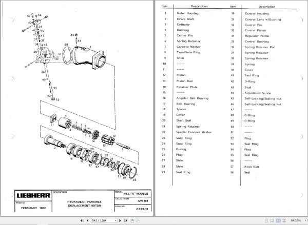
2.3.91 Hydraulic variable flow motor A6V (Hydromatik) A 900 – A 942
2.3.92 Hydraulic fixed displacement motor LMF (Liebherr) A 900 – A 942
2.3.96 Hydraulic variable flow motor LMF (Liebherr) A 902 – A 922
2.4 Air pressure system
2.4.01 Pressure chart
2.4.05 Description and fiunction A 900
2.4.06 Description and function A 902 / A 912 / A 922
2.4.20 Description and function of components
2.5 Rotary connection
2.5.02 Five-way air rotary connection
2.5.05 Oil rotary connection “Grau”
2.5.06 Oil rotary connection “Sigma”
2.5.08 Oil rotary connection “Liebherr”
2.6 Electrical system
2.6.01 General notes
2.6.02 Battery handling and maintenance
2.6.03 Starter
2.6.04 Alternator
2.6.05 Glow plug
2.6.08 Electrical system A 900
2.6.10 Electrical system A 902 – A 922
2.6.15 Electrical system A 902 – A 922
2.7 Heater / Air conditioner
2.7.05 Engin oil heater
2.7.08 Cab heater installation A/ R 900
2.7.08 Cab heater installation A 902 – A 922
2.7.09 Cab heater installation A 942
2.7.10 Cab heater D1L
3.1 Two speed gear box
3.1.03 Remove and install / Gearbox
3.1.05 Diassembly and assembly / Two speed gear box
3.2 Front and real axle / Differential
3.2.01 Examples of Gleason gear
3.2.03 Removing and installation of front axle and differential
3.2.04 Removing and installation of rear axle and differential
3.2.05 Diassembly and assembly of differential – Carrier A1
3.2.06 Diassembly and assembly of differential – Carrier B
3.2.07 Diassembly and assembly of differential – Carrier C
3.2.10 Removing and installing / Front Axle
3.2.11 Removing and installing / Front axle
3.2.15 Removing and installing / Rear axle
3.3 Hydrostatic steering
3.3.01 Hydrostatic steering
3.3.05 Servostat
3.3.06 Flow indicator
3.4 Oscillating axle support
3.4.05 Oscillating axle support A 900 / A 942
3.4.06 Oscillating axle suppert A 902 – A 922
3.5 Brakes
3.5.01 Pressure chart and instructions
3.5.02 Removing and installing – Four wheel brake
3.5.03 Construction and funktion of brakes / Bleeding
3.5.04 Function and adjusting – Hydraulic simplex brake
3.5.05 Function and repair of master cylinder
3.5.06 Troubleshooting
3.5.10 Function and instructions of brake (Pneumatic)
3.5.11 Function and adjusting of brake (Mechanical)
3.5.12 Troubleshooting
3.6 Swing ring
3.6 Remove and install swing ring
5.2 Special equipment / accessory kits
5.2.02 Overload warning device / General data
5.2.03 Overload warning device A 900
5.2.04 Overload warning device A/ R 902 – A/R 922
5.2.05 Overload warning device A 902 – A 922
5.2.06 Overload warning device A/R 942
5.2.09 Hoist limit
5.2.10 Load check valve
5.2.11 Load check valve / Leckoil free
5.2.12 Atrachment AS1 A/R 900 -902
5.2.13 Attachment AS1 A/R 912 – R 932
5.2.14 Attachment AS1 A/R 942
5.2.15 Attachment for elevated cab A 912 – A 922
5.2.16 Attachment for elevated cab A 902 – A 922
5.2.18 Attachment ASH A/R 900
5.2.19 Attachment ASH A/R 900 – R 932
5.2.20 Attachment ASH A 942
5.2.22 Attachment AHS1 A/R 902 – R 932
5.2.24 Attachment AHS2 A/R 892 – A 922
5.2.26 Attachment AHS3 A/R 902 – A 922
5.2.30 Grapple Attachment
5.2.31 Grapple rotary device
5.2.32 Quick change coupling
5.2.34 Pin lock
5.2.35 Limit switch for industrial attachment
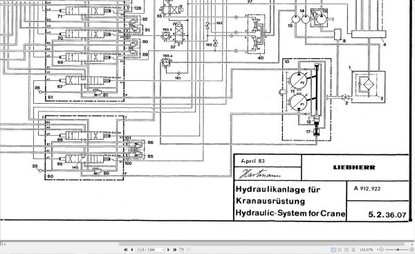
5.2.36 Crane attachment
5.2.38 Industrial crane
5.2.40 Adjustable cab
5.2.42 Dumping attachment
5.2.44 Dozer blade
5.2.46 Outrigger control
5.2.47 Slipring rotary connenction
5.2.50 Hydraulic hammer
5.2.51 Special attachment
5.3 Hydraulic cylinder
5.3.01 Hydraulic cylinder – Torque values
5.3.02 Hydraulic cylinder – Removing and installing
5.3.05 Hydraulic cylinder without cushioning
5.3.10 Hydraulic cylinder without/with cushioning
5.3.15 Hydraulic cylinder – Steering
5.3.21 Hydraulic cylinder A/R 902
5.3.22 Hydraulic cylinder A/R 912
5.3.23 Hydraulic cylinder A/R 922
5.3.25 Hydraulic cylinder A/R 942

REALEASE :
04.07.2022
REALEASE :
04.07.2022

REALEASE :
25.03.2022
REALEASE :
25.03.2022
REALEASE :
01.13.2022

REALEASE :
02.03.2022
REALEASE :
02.03.2022

REALEASE :
29.03.2022
REALEASE :
29.03.2022

REALEASE :
23.03.2022
REALEASE :
23.03.2022

REALEASE :
16.09.2022
REALEASE :
16.09.2022

REALEASE :
02.03.2022
REALEASE :
02.03.2022
 Automotive - Heavy Equipment - Truck & Bus - Forklift - Crane