
1 ITEMVIEW CART

Total: 30.00

Expert Support
Full Speed
100% Working
100 USD
Contents:
1 General
1.10 Safety instructions
1.20 Tightening torques (WN 4037 K)
1.21 Tightening torques
1.22 Assembly instruction for hydraulilc cylinder WN 4121 C
1.24 Assembly instruction for hydraulic cylinder WN 4122 B
1.25 Tightening torques for piston rod bearing screws
1.40 Filling quantities
1.50 Lubricants and process chemicals
1.55 TE_ML05 lubricant list
1.56 TE_ML07 lubricant list
2 Tools
2.01 Special tools – general information
2.02 Special tools for diesel engines
2.05 Special tools for hydraulic systems
2.06 Special tools for electrical equipment
2.07 Special tools for gears
2.08 Special tools for axles (ZF)
2.12 Assembly tools for hydraulic cylinders
2.13 Mounting device for piston rod bearings
2.14 Slotted nut wrench for slewing gear mechanism
2.15 Mounting device for multi-disk brake
3 Technical data / maintenance instructions
3.10 Technical data A 900 C LI
3.14 Technical data of A 904 C LI
3.20 Maintenance and inspection schedule
3.24 Maintenance and inspection schedule
3.30 Lubricating charts
3.40 Adjustment protocol V2.10 A 900 C LI-
3.46 Adjustment protocol V2.11 A 904 LI
3.60 Adjustment guideline for hydraulic system
4 Drive motor
4.11 Technical data of diesel engines
5 Coupling / pump distribution gear
5.10 Coupling
6 Hydraulic system
6.01 LSC system
6.20 Design of hydraulic system
6.30 Hydraulic system A 900 C, starting with 14675
6.32 Hydraulic system A 904 C, starting with 16000
7 Hydraulic components
7.01 Hydraulic pumps – dismantling, installation and initial operation
7.02 LPV variable displacement pump
7.05 Variable-displacement pump DPVO 165
7.20 FMF hydraulic fixed displacement motor
7.25 LMV regulating motor
7.30 Hydraulic cylinder
7.31 Extension and retraction times of hydraulic cylinders
7.32 Hydraulic double plunger cylinder
7.40 Control oil and regulating unit
7.42 Pilot control unit 1x (travelling foot pedal)
7.44 Pilot control valve 2 x
7.46 Pilot control valve 2 x
7.48 Pilot control valve 4 x
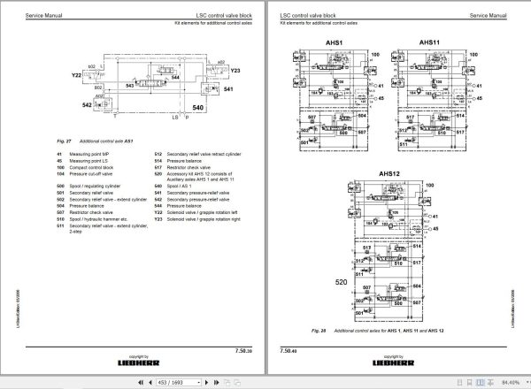
7.50 LSC control valve block
7.68 Leak oil check at control valve blocks
7.70 Rotary connection 6 x
7.75 Rotary connection 7 x
7.80 TC valve
7.85 Double stop valve for outrigger support
7.95 Accumulator
8 Electrical system
8.01 Overview of electrical symbols
8.10 Component arrangement
8.32 Electrical system
8.44 Operating symbols on the operator’s platform
8.45 List of electric kits
8.70 BST excavator control (version 2.. or V5..)
8.71 Monitoring display
8.72 Monitoring display
8.79 Control panel
8.80 Error code list
8.82 Slip ring rotary connection
9 Slewing gear mechanism
9.10 Slewing gear mechanism
9.20 Slewing gear brake
10 Slewing ring
10.10 Slewing ring
11 Transmission
11.10 2 HL 100 transmission
11.30 HBGV block for 2 HL 100 transmission
12 Axles
12.01 Tyres
12.10 APL – B 755 steering axle with multi-disc brake
12.12 AP – B 755 rigid axle with drum brake
12.16 Differential for AP / APL – B 755 axles
12.20 APL – B 765 steering axle with multi-disc brake
12.22 AP – B 765 rigid axle with drum brake
12.24 AP – B 765 rigid axle with multi-disc brake
12.26 Differential for AP / APL – B 765 axles
13 Steering
13.10 Hydraulic steering system
13.18 Joystick steering
13.20 Servostat
13.25 Steering valve
13.30 Steering cylinder
13.32 Steering cylinder
14 Oscillating axle support
14.10 Oscillating axle support with automatic control
14.20 Support cylinder
15 Brake system
15.05 Operating pressures of the brake system
15.10 Hydraulic brake system
15.20 Compact brake block
16 Special equipment / accessory kits
16.01 Pipe fracture safety valve for hoist cylinder
16.06 Overload warning system
16.08 Switchable overload warning system
16.15 Hydraulic quick change adapter
16.18 LIKUFIX hydraulic coupling system
16.19 Hydraulic-electric LIKUFIX coupling system
16.20 Pressure and flow reduction
16.22 Hydraulic hammer
16.30 Speeder kit
16.40 Accessory kit AS1
16.43 Accessory kit AHS 1
16.45 Accessory kit AHS 11
16.46 Accessory kit AHS 11 with Tool Control
16.48 Accessory kit AHS 12
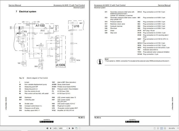
16.49 Accessory kit AHS 12 with Tool Control
16.60 Hydraulic operator’s cab elevation system
16.62 Individual control
16.64 Dozer blade
16.66 Refuelling pump
16.68 Bypass filter
16.69 LIEBHERR bypass filter
16.70 Reversible fan drive
17 Operators’s cab / heating and air-conditioning
17.30 Auxiliary heater
17.40 Inspection and repair instructions for heating and air-conditioning system
17.50 Heating and air-conditioning system
18 Undercarriage / uppercarriage / attachments
18.50 Repair instructions for lubrication hoses
18.51 Central lubrication system
18.53 Semi-automatic central lubrication system
18.54 Fully automatic central lubricating system
18.56 Central lubrication pump
18.58 SX-E progressive distributor
18.59 MX-F progressive distributor
19 Arrangement of Tanks

REALEASE :
29.03.2022
REALEASE :
29.03.2022

REALEASE :
16.09.2022
REALEASE :
16.09.2022

REALEASE :
23.03.2022
REALEASE :
23.03.2022
REALEASE :
01.13.2022

REALEASE :
04.07.2022
REALEASE :
04.07.2022

REALEASE :
25.03.2022
REALEASE :
25.03.2022

REALEASE :
02.03.2022
REALEASE :
02.03.2022

REALEASE :
02.03.2022
REALEASE :
02.03.2022
Automotive - Heavy Equipment - Truck & Bus - Forklift - Crane