
0 ITEMSVIEW CART


✓
Expert Support
✓
Full Speed
✓
100% Working
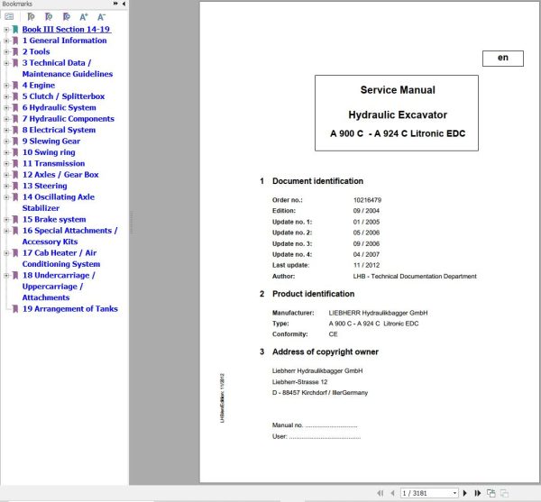
Liebherr Excavator A900C to A924C Litronic EDC Service Manual 10216479
Size: 103.69 MB
Format: PDF
Language: English
Brand: Liebherr
Type of Machine: Excavator
Type of Manual: Service Manual, Electric and Hydraulic Diagrams
Model: Liebherr
A 900 C LI
A 904 C LI
A 914 C LI
A 924 C LI
A 924 C HD LI
Engine: D 934 SA6, D 934 LA6, (Tier 3 – Stage III-A)
Order Number: 10216479
Publication Date: 2012
Number of Pages: 3181 Pages
150 USD
- Description
Description
Contents:
1 General Information
1.01 Standards and regulations
1.02 Changes and modifications to series
1.10 Safety instructions
1.21 Tightening torques for fittings
1.40 Filling quantities
1.51 Fuels, lubricants and process chemicals
1.55 TE_ML05 lubricant list
1.56 TE_ML07 lubricant list
1.60 Conservation guidelines
2 Tools
2.01 Special tools – general
2.02 Special tools for diesel engines
2.05 Special tools for hydraulic system
2.06 Special tools for electrical equipment
2.07 Special tools for gears
2.08 Special tools for axles (ZF)
2.09 Special tools for axles (ZF)
2.10 Special tools for axles (Kessler)
2.12 Assembly tools for hydraulic cylinders
2.13 Mounting device for piston rod bearings
2.14 Slotted nut wrench for slewing gear mechanism
2.15 Mounting device for multi-disk brake
3 Technical Data / Maintenance Guidelines
3.05 Type overview A 904 C LI
3.06 Type overview A 914 C LI
3.11 Technical data A 900 C LI
3.15 Technical data A 904 C LI
3.16 Technical data A 914 C LI
3.17 Technical data of A 924 C LI
3.18 Technical data of A 924 C HD LI
3.21 Inspection and maintenance schedule
3.25 Inspection and maintenance schedule
3.27 Inspection and maintenance schedule
3.30 Lubricating charts
3.41 Adjustment protocol V4.3 A 900 C LI
3.42 Adjustment protocol V4.4 A 900 C LI
3.43 Adjustment protocol V4.7 A 900 C LI
3.44 Adjustment protocol V4.7 A 900 C LI
3.45 Adjustment protocol V4.8 A 900 C LI
3.46 Adjustment protocol V4.4 A 904 C LI
3.47 Adjustment protocol V4.7 A 904 C LI
3.48 Adjustment protocol V4.8 A 904 C LI
3.49 Adjustment protocol V4.8.1 A 904-1
3.50 Adjustment protocol V4.6 A 914 C LI
3.51 Adjustment protocol V4.7 A 914 C LI
3.52 Adjustment protocol V4.8 A 914 C LI
3.55 Adjustment protocol V4.6 A 924 C LI
3.56 Adjustment protocol V4.7 A 924 C LI
3.57 Adjustment protocol V4.8 A 924 C LI
3.61 Adjustment guidelines for hydraulic system
3.62 Checking and adjusting tasks V4.7
3.63 Checking and adjusting tasks V4.8
3.70 Adjustment guidelines for hydraulic system
3.71 Checking and adjusting tasks V4.7
3.72 Checking and adjusting tasks V4.8
3.80 Adjustment protocol (kits)
4 Engine
4.05 Bleeding the fuel system
4.12 Technical data of diesel engines
4.13 Technical data of diesel engines
4.25 Installation and check list
4.27 Liebherr diesel particle filter accessory kit
4.40 Datalogger version 2.3.00
4.41 Datalogger software version 2.3.09
5 Clutch / Splitterbox
5.10 Coupling
5.20 Pump distributor gear
6 Hydraulic System
6.01 LSC system
6.10 Grab control
6.21 Layout of hydraulic system
6.22 Layout of hydraulic system
6.31 Hydraulic system A 900 C, from 24677
6.32 Hydraulic system A 900 C, from 54182
6.34 Hydraulic system A 904 C, from 30580
6.35 Hydraulic system A 904 C, from 35343
6.36 Hydraulic system A 904 C, from 39333
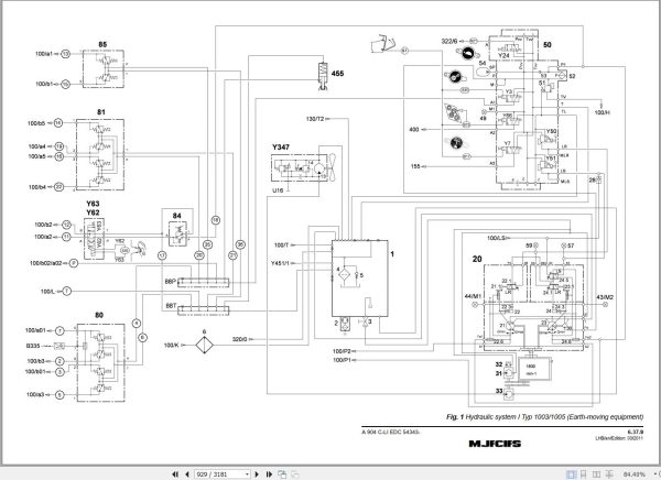
6.37 Hydraulic system A 904 C from 54343
6.38 Hydraulic system A 904 C Li IND from 54196
6.40 Hydraulic system A 914/A924 C, from 34519
6.41 Hydraulic system A 914/A924 C, from 49928
7 Hydraulic Components
7.01 Hydraulic pumps – dismantling, installation and initial operation
7.05 Variable-displacement pump DPVO 165
7.06 DPVO 165 variable-displacement pump
7.07 DPVP 108 double variable-displacement pump
7.20 FMF hydraulic fixed displacement motor
7.22 HMF 75-02P hydraulic fixed-displacement motor
7.27 DMVA regulating motor (travel drive)
7.28 DMVA regulating motor (travel drive)
7.30 Hydraulic cylinder
7.31 Extension and retraction times of hydraulic cylinders
7.32 Hydraulic double plunger cylinder
7.41 Control oil and regulating unit
7.42 Pilot control unit 1x (travelling foot pedal)
7.44 Pilot control valve 2 x
7.46 Pilot control valve 2 x
7.49 Pilot control unit 4x
7.51 LSC control valve block
7.55 LSC pilot plate
7.60 Cooling unit
7.61 Cooling unit
7.68 Leak oil check at control valve blocks
7.70 Rotary connection 6 x
7.75 Rotary connection 7 x
7.95 Accumulator
8 Electrical System
8.01 Overview of electrical symbols
8.02 Notes regarding the electrical system
8.12 Arrangement of components
8.14 Arrangement of components
8.34/E3 Electrical system (construction model)
8.38/E3 Electrical system (industrial model)
8.40/E3 Electrical system (construction model)
8.42/E3 Electrical system (industrial model)
8.44 Operating symbols on the operator’s platform
8.50 LIEBHERR POWER EFFICIENCY (LPE)
8.68 Excavator control system BST from 4…..
8.73 Monitoring display from version 4.4/4.5/4.6
8.74 Monitoring display from version 4.7
8.75 Monitoring display from version 4.8/V4.8.1
8.79 Control panel
8.80 Error code list
8.82 Slip ring rotary connection
8.99 Self-holding mechanism for quick-change adapter locking
8.100 Directory of electrical kits
8.101 Magnet systems
8.102 Generator drive hydraulic LIKUFIX
8.103 Hydraulic operator’s cab elevation
8.104 Automatic central lubrication system
8.105 Lifting boom when grapple closes
8.106 Travel alarm systems
8.107 Overload warning system
8.108 Stick cylinder shutdown (with angle sensor R70/B317)
8.109 Industrial shutdown proximity switch
8.110 Quick change adapter
8.111 Back-up alarm system
8.112 Joystick steering
8.113 Individual control 4-point support
8.114 Individual control 4-point support
8.115 Outrigger control
8.116 Four-wheel steering
8.117 Forward/reverse travel in left handle
8.118 Auxiliary heater
8.119 Stroke limitation/electronic stroke limitation
8.120 Changeover valve
8.121 Mower rake accessory kit
8.122 Rotating stick with changeover valve
8.123 AHS12 changeover
8.124 Puritech particle filter
8.125 Grab Control
8.126 Individual control with dozer blade
8.127 Hoist cylinder protection
8.128 Pipe layer
8.129 Proportional control
8.130 Changeover proportional control AHS11/12
8.131 Add-on axle (3rd axle)
8.132 Self-holding quick change adapter
8.133 Reversible fan drive
8.134 Rear space monitoring
9 Slewing Gear
9.10 Slewing gear mechanism
9.21 Slewing gear brake
9.25 Positioning slewing brake
10 Swing ring
10.10 Slewing ring
11 Transmission
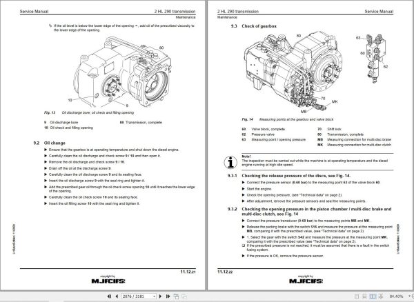
11.12 2 HL 290 transmission
11.35 HBGV block for transmission 2 HL 290
12 Axles / Gear Box
12.01 Tyres
12.03 Use of special tool (Kessler axles)
12.07 Steering drive axle LT 71
12.08 Rigid axle D 71
12.40 MS-E 3060 steering axle
12.42 MT-E 3060 rigid axle
12.44 MS/MT-E 3060 input unit and differential
12.50 MS-E 3070 steering axle
12.52 MT-E 3070 rigid axle
12.54 MS/MT-E 3070 input unit and differential
13 Steering
13.10 Hydraulic steering system
13.15 Four-wheel steering
13.18 Joystick steering
13.20 Servostat
13.25 Steering valve
13.31 Steering cylinder
13.33 Steering cylinder
14 Oscillating Axle Stabilizer
14.10 Oscillating axle support with automatic control
14.20 Support cylinder
15 Brake system
15.05 Operating pressures of the brake system
15.10 Hydraulic brake system
15.20 Compact brake block
16 Special Attachments / Accessory Kits
16.02 Pipe fracture safety valve for stick cylinder
16.03 Pipe fracture safety valve for boom cylinders
16.04 Pipe fracture safety valve for boom cylinders
16.05 Pipe fracture safety unit for stick cylinder
16.06 Overload warning system
16.08 Switchable overload warning system
16.10 Tool management
16.14 Camera monitoring system
16.15 Hydraulic quick-change adapter
16.16 Boom cylinder protection system
16.18 LIKUFIX hydraulic coupling system
16.19 Hydraulic-electric LIKUFIX coupling system
16.20 Pressure and flow reduction
16.21 Pressure and flow reduction
16.22 Hydraulic hammer
16.23 Pipe layer
16.24 Swivel rotator TR-20/TR-25
16.32 Generator drive accessory kit
16.34 Generator conversion kit for LIKUFIX
16.35 Installation instruction for V-belt drive
16.40 Accessory kit AS1
16.41 Accessory kit AS1
16.43 Accessory kit AHS 1
16.46 AHS 11 accessory kit with Tool Control
16.49 AHS 12 accessory kit with Tool Control
16.50 Accessory kit AHS 11 / AHS 12 with Tool Control
16.51 Switching control (AHS11/AHS12)
16.52 AS1 proportional control
16.53 AS1 proportional control
16.54 AHS 11 proportional control
16.55 AHS 11 proportional control
16.56 AHS 12 proportional control
16.57 AHS 12 proportional control
16.58 Proportional control changeover AHS11/12
16.60 Hydraulic operator’s cab elevation system
16.61 Hydraulic operator’s cab elevation system
16.62 Individual control
16.64 Dozer blade
16.65 Dozer blade
16.66 Refuelling pump
16.68 Bypass filter
16.69 LIEBHERR bypass filter
16.70 Reversible fan drive
16.71 Reversible fan drive (manual/automatic)
16.72 Reversible fan drive (manual/automatic)
16.74 Mower rake accessory kit
16.76 Stroke and stick limitation with proximity switches
16.77 Stroke limitation with angle sensors
16.80 Stick cylinder shut-down with proximity switch
16.81 Stick cylinder shut-down with proximity switch
16.82 Stick cylinder shut-down with proximity switch
16.85 Electronic stick cylinder shut-down
16.86 Electronic stick cylinder shut-down
17 Cab Heater / Air Conditioning System
17.30 Auxiliary heater
17.40 Inspection and repair instructions for heating and air-conditioning system
17.50 Heating and air-conditioning system
18 Undercarriage / Uppercarriage / Attachments
18.01 Fixture of operator’s cab elevation system
18.50 Repair instructions for lubrication hoses
18.51 Central lubrication system
18.53 Semi-automatic central lubrication system
18.54 Fully automatic central lubricating system
18.56 Central lubrication pump
18.58 SX-E progressive distributor
18.59 MX-F progressive distributor
19 Arrangement of Tanks
Related Products
-
Liebherr Mining Excavators 84.88Gb PDF Updated 01.2022 Service Manuals DVD
USDLiebherr Mining Excavators 84.88Gb PDF Updated 01.2022 Service Manuals DVDSize: 84.88 Gb (PDF Files)Type of vehicle: Mining ExcavatorsType of manual: Service ManualLanguage: EnglishBrand: LiebherrFormat: PDFUpdate: 01.2022OS: All WindowsAmount of DVD: 1 DVDREALEASE :
01.13.2022
-
Liebherr Crane LTM 1800 Service Manual Operators Manual Schematic
Original price was: 300.180Current price is: 180. USDThey are PDF Service Manual Operators Manual Schematic Manual, You need to use these to repair your vehicle.Hot-40%
REALEASE :
16.09.2022
REALEASE :
16.09.2022
-
Liebherr Wheel Loader Updated 03.2022 Full Service Manuals DVD PDF
Original price was: 700.340Current price is: 340. USDLiebherr Wheel Loader 24.29GB Updated 03.2022 Full Service Manuals DVD PDFSize: 24.29 GB (PDF Files)Type of Vehicle: Wheel LoadersType of Document: Service ManualsFormat: PDFLanguage: EN, ZH, DEBrand: LiebherrDate Updated: 03.2022OS: All Windows 32 & 64 bitHigh-Speed Link DownloadDETAIL CONTENTS: “CLICK HERE“Hot-51%
REALEASE :
02.03.2022
REALEASE :
02.03.2022
-
Liebherr Crane HS HSG Operating Manual Spare Parts List Technical Information PDF DVD
Original price was: 1,500.540Current price is: 540. USDLiebherr Crane HS HSG Operating Manual Spare Parts Catalogue Technical Information DVD Size: 2.17 GB Fomat: PDF Language: EN,DE Brand: Liebherr Type of machine: Liebherr Crawler Crane Window: All Win 32 and 64 Bit, Mac OS Type of document: Liebherr Crane HS Operating Manual Liebherr Crane HS Spare Parts Catalogue Liebherr Crane HS Technical information Liebherr Crane HS Electrical Circuit Diagram Liebherr Crane HS Hydraulic Circuit DiagramHot-64%
REALEASE :
04.07.2022
REALEASE :
04.07.2022
-
Liebherr Wheeled and Crawler Excavators Updated 03.2022 Service Manuals DVD PDF
Original price was: 800.340Current price is: 340. USDLiebherr Wheeled and Crawler Excavators 48.3GB Updated 03.2022 Service Manuals DVD PDFSize: 48.3 GB (PDF Files)Format: PDFLanguage: EN, DEBrand: LiebherrDate Updated: 03.2022OS: All Windows 32 & 64bitType of Vehicle: Wheeled and Crawler ExcavatorsType of Document: Service ManualsHigh-Speed Link Download DETAIL CONTENTS: “CLICK HERE“Hot-58%
REALEASE :
02.03.2022
REALEASE :
02.03.2022
-
Liebherr Mobile Crawler Cranes PDF Spare Parts List DVD
Original price was: 200.140Current price is: 140. USDLiebherr Mobile & Crawler Cranes 1.24 GB PDF Spare Parts Catalog DVDSize: 1.24 GBFormat: PDF, winrarBrand: LiebherrLanguages: English, Deutsch, Spanish, Russian, French, PortugueseType of Machine: Mobile Crane, Crawler Crane, Rough Terrain Crane, Tower CraneType of Document: Spare Parts CatalogsNumber of DVD: 1 DVDOS: Windows Vista, XP, 7, 8.1, 8, 10, MacOSHigh-Speed DownloadDETAIL CONTENTS: “CLICK HERE“Hot-30%
REALEASE :
29.03.2022
REALEASE :
29.03.2022
-
Liebherr Crawler Crane with Telescopic Boom LTR 1100 100 Ton Operator Manual Diagnostics LICCON Wiring Diagram
Original price was: 400.160Current price is: 160. USDLiebherr Crawler Crane with Telescopic Boom LTR 1100 100 Ton Operator Manual, Diagnostics LICCON & Wiring Diagram Size: 734 Mb Language: English_EN Format: PDF Model: LTR 1100 Capacity: 100 Ton SN: Z97542 Diesel Engine: D944 A7 DETAIL CONTENTS: “CLICK HERE“Hot-60%
REALEASE :
23.03.2022
REALEASE :
23.03.2022
-
LIEBHERR LTM 1095-5.1 95 Ton Operator Manual Diagnostics LICCON Wiring Schematic PDF
Original price was: 200.60Current price is: 60. USDLIEBHERR LTM 1095-5.1 95 Ton Operator Manual, Diagnostics LICCON & Wiring DiagramSize: 77.3 MBFormat: PDFlanguage: EnglishBrand: LiebherrType of machine: Mobile CraneType of document:Model: LIEBHERR LTM 1095-5.1DETAIL CONTENTS: “CLICK HERE“Hot-70%
REALEASE :
25.03.2022
REALEASE :
25.03.2022
