
0 ITEMSVIEW CART


✓
Expert Support
✓
Full Speed
✓
100% Working
Liebherr Excavator A900C – ZW EDC Litronic Service Manual 10814267
Size: 78.57 MB
Format: PDF
Language: English
Brand: Liebherr
Type of Machine: Excavator
Type of Manual: Service Manual, Electric and Hydraulic Diagrams
Model: Liebherr A900C – ZW EDC Litronic Excavator
Engine: D 934 S A6 (Tier 3 – Stage III-A)
Order Number: 10814267
Publication Date: 2012
Number of Pages: 2035 Pages
100 USD
- Description
Description
Contents:
1 General
1.02 Modifications of series
1.10 Safety instructions
1.11 Safety instructions
1.15 Tightening torques for flange connections
1.20 Tightening torques (WN 4037 K)
1.21 Tightening torques
1.22 Assembly instruction for hydraulilc cylinder WN 4121 C
1.24 Assembly instruction for hydraulic cylinder WN 4122 B
1.25 Tightening torques for piston rod bearing screws
1.40 Filling quantities
1.51 Fuels, lubricants and process chemicals
1.55 TE_ML05 lubricant list
1.56 TE_ML07 lubricant list
1.60 Conservation guidelines
2 Tools
2.01 Special tools – general
2.02 Special tools for diesel engines
2.03 Special tools for ZW equipment
2.05 Special tools for hydraulic system
2.06 Special tools for electrical equipment
2.07 Special tools for gears
2.08 Special tools for axles (ZF)
2.09 Special tools for axles (Kessler)
2.12 Assembly tools for hydraulic cylinders
2.13 Mounting device for piston rod bearings
2.14 Slotted nut wrench for slewing gear mechanism
2.15 Mounting device for multi-disk brake
3 Technical data / Maintenance instructions
3.05 Type overview of A 900 C ZW Litronic
3.12 Technical data
3.21 Inspection and maintenance schedule
3.30 Lubricating charts
3.35 Adjustment of ZW rail guide system
3.42 Adjustment protocol V4.7.2
3.43 Adjustment protocol V4.8.2
3.47 Checking and adjusting tasks
3.50 Maintenance schedule (scheduled inspection)
3.60 Warning and information signs on A 900 C ZW
4 Drive motor
4.05 Bleeding the fuel system
4.12 Technical data of diesel engines
4.25 Installation and check list
4.27 Liebherr diesel particle filter accessory kit
4.40 Datalogger version 2.3.00
4.41 Datalogger software version 2.3.09
5 Coupling / Pump distributor gear
5.10 Coupling
5.20 Pump distributor gear
6 Hydraulic system
6.01 LSC system
6.31 Layout of hydraulic system
6.42 Hydraulic system A 900 C ZW, EDC 31354-
6.43 Hydraulic system A 900 C ZW EDC 50658
6.44 Hydraulic system A 900 C ZW EDC 53810
6.60 Function of ZW rail guide system
6.61 Function of ZW rail guide system
7 Hydraulic components
7.01 Hydraulic pumps – dismantling, installation and initial operation
7.05 Variable-displacement pump DPVP 108
7.10 Variable-displacement pump A10V0
7.20 FMF hydraulic fixed displacement motor
7.27 DMVA regulating motor (travel drive)
7.28 DMVA regulating motor (travel drive)
7.30 Hydraulic cylinder
7.31 Extension and retraction times of hydraulic cylinders
7.32 Hydraulic double plunger cylinder
7.41 Control oil and regulating unit
7.49 Pilot control unit 4x
7.51 Control block LSC
7.68 Leak oil check at control valve blocks
7.70 Rotary connection 6 x
7.75 Rotary connection 7x
7.80 Axle control block of the rail guide
7.82 Axle control block of the rail guide
7.95 Accumulator
7.85 Changeover travel / support
8 Electrical system
8.01 Overview of electrical symbols
8.02 Notes regarding the electrical system
8.12 Arrangement of components
8.32 Electrical system (basic machine)
8.34 Electical system with installation kits and wiring harnesses
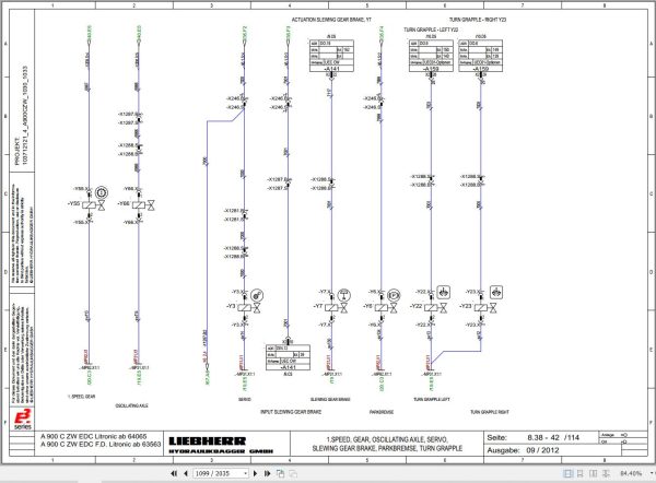
8.38 Electical system with installation kits and wiring harnesses
8.44 Operating symbols on the operator’s platform
8.50 Data logger
8.60 Electronically controlled working and travelling pedal
8.62 Calibration of the electric foot pedals
8.70 ZW monitoring display (TDS01)
8.72 Monitoring display from V.4.7.2
8.79 Control panel
8.80 Error code list
8.81 Emergency actuation (emergency operation)
8.82 Slip ring rotary connection
8.90 Resistance measurement
8.99 Self-holding mechanism for quick-change adapter locking
9 Slewing gear mechanism
9.10 Slewing gear mechanism
9.21 Slewing gear brake
9.25 Positioning slewing brake
10 Slewing ring
10.10 Slewing ring
11 Transmission
11.12 2 HL 290 transmission
11.35 HBGV block for transmission 2 HL 290
12 Axles / Rail guide system
12.35 Tyres
12.40 ZW rail guide
12.50 MS-E 3070 steering axle
12.52 MT-E 3070 rigid axle
12.54 MS/MT-E 3070 input unit and differential
12.70 Conversion of rail gear for narrow gauge
12.90 Measuring of the wheel flange of the rail chassis
12.91 Measuring of tyre track width
12.95 Wear limits
13 Steering
13.10 Hydraulic steering system
13.25 Steering valve
13.33 Steering cylinder
14 Oscillating axle support
14.10 Oscillating axle support with automatic control
14.20 Support cylinder
15 Brake system / Air pressure system
15.05 Operating pressures of the brake system
15.10 Hydraulic brake system
15.20 Compact brake block
15.51 Compressed air – wagon brake system
16 Special equipment / Accessory kits
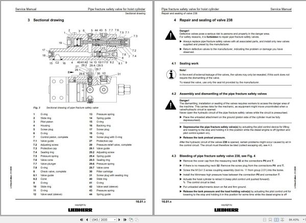
16.01 Pipe fracture safety valve for hoist cylinder
16.02 Pipe fracture safety valve for stick cylinder
16.03 Pipe fracture safety valve for boom cylinders
16.10 Optional equipment control
16.11 Terminal assignment of attachments
16.12 Changeover bucket – closing cylinder
16.13 LIEBHERR hydro magnet
16.14 Camera monitoring system
16.15 Hydraulic quick-change adapter
16.18 LIKUFIX hydraulic coupling system
16.19 Hydraulic-electric LIKUFIX coupling system
16.21 Pressure and flow reduction
16.22 Hydraulic hammer
16.24 Swivel rotator TR-20/TR-25
16.40 Accessory kit AS1
16.50 Stroke and boom limitation
16.52 Adjustment of the stroke and boom limitation parameters
16.54 Inclination sensor
16.55 Changeover position pressure control
16.56 Switching between position and pressure control
16.57 Emergency hydraulics
16.60 Refuelling pump
16.62 Individual control
16.65 Bypass filter
16.69 LIEBHERR bypass filter
16.75 3rd axle for road travel
17 Operator’s cab / Heating and air-conditioning
17.30 Auxiliary heater
17.40 Inspection and repair instructions for heating and air-conditioning system
17.50 Heating and air-conditioning system
18 Rail roader installations / Attachments
18.50 Repair instructions for lubrication hoses
18.51 Central lubrication system
170.015 Semi-automatic central lubrication system
18.54 Fully automatic central lubricating system
18.56 Central lubrication pump
18.58 SX-E progressive distributor
18.59 MX-F progressive distributor
19 Tank arrangement
Related Products
-
Liebherr Mobile Crawler Cranes PDF Spare Parts List DVD
Original price was: 200.140Current price is: 140. USDLiebherr Mobile & Crawler Cranes 1.24 GB PDF Spare Parts Catalog DVDSize: 1.24 GBFormat: PDF, winrarBrand: LiebherrLanguages: English, Deutsch, Spanish, Russian, French, PortugueseType of Machine: Mobile Crane, Crawler Crane, Rough Terrain Crane, Tower CraneType of Document: Spare Parts CatalogsNumber of DVD: 1 DVDOS: Windows Vista, XP, 7, 8.1, 8, 10, MacOSHigh-Speed DownloadDETAIL CONTENTS: “CLICK HERE“Hot-30%
REALEASE :
29.03.2022
REALEASE :
29.03.2022
-
LIEBHERR LTM 1095-5.1 95 Ton Operator Manual Diagnostics LICCON Wiring Schematic PDF
Original price was: 200.60Current price is: 60. USDLIEBHERR LTM 1095-5.1 95 Ton Operator Manual, Diagnostics LICCON & Wiring DiagramSize: 77.3 MBFormat: PDFlanguage: EnglishBrand: LiebherrType of machine: Mobile CraneType of document:Model: LIEBHERR LTM 1095-5.1DETAIL CONTENTS: “CLICK HERE“Hot-70%
REALEASE :
25.03.2022
REALEASE :
25.03.2022
-
Liebherr Crane LTM 1800 Service Manual Operators Manual Schematic
Original price was: 300.180Current price is: 180. USDThey are PDF Service Manual Operators Manual Schematic Manual, You need to use these to repair your vehicle.Hot-40%
REALEASE :
16.09.2022
REALEASE :
16.09.2022
-
Liebherr Crawler Crane with Telescopic Boom LTR 1100 100 Ton Operator Manual Diagnostics LICCON Wiring Diagram
Original price was: 400.160Current price is: 160. USDLiebherr Crawler Crane with Telescopic Boom LTR 1100 100 Ton Operator Manual, Diagnostics LICCON & Wiring Diagram Size: 734 Mb Language: English_EN Format: PDF Model: LTR 1100 Capacity: 100 Ton SN: Z97542 Diesel Engine: D944 A7 DETAIL CONTENTS: “CLICK HERE“Hot-60%
REALEASE :
23.03.2022
REALEASE :
23.03.2022
-
Liebherr Wheeled and Crawler Excavators Updated 03.2022 Service Manuals DVD PDF
Original price was: 800.340Current price is: 340. USDLiebherr Wheeled and Crawler Excavators 48.3GB Updated 03.2022 Service Manuals DVD PDFSize: 48.3 GB (PDF Files)Format: PDFLanguage: EN, DEBrand: LiebherrDate Updated: 03.2022OS: All Windows 32 & 64bitType of Vehicle: Wheeled and Crawler ExcavatorsType of Document: Service ManualsHigh-Speed Link Download DETAIL CONTENTS: “CLICK HERE“Hot-58%
REALEASE :
02.03.2022
REALEASE :
02.03.2022
-
Liebherr Mining Excavators 84.88Gb PDF Updated 01.2022 Service Manuals DVD
USDLiebherr Mining Excavators 84.88Gb PDF Updated 01.2022 Service Manuals DVDSize: 84.88 Gb (PDF Files)Type of vehicle: Mining ExcavatorsType of manual: Service ManualLanguage: EnglishBrand: LiebherrFormat: PDFUpdate: 01.2022OS: All WindowsAmount of DVD: 1 DVDREALEASE :
01.13.2022
-
Liebherr Crane HS HSG Operating Manual Spare Parts List Technical Information PDF DVD
Original price was: 1,500.540Current price is: 540. USDLiebherr Crane HS HSG Operating Manual Spare Parts Catalogue Technical Information DVD Size: 2.17 GB Fomat: PDF Language: EN,DE Brand: Liebherr Type of machine: Liebherr Crawler Crane Window: All Win 32 and 64 Bit, Mac OS Type of document: Liebherr Crane HS Operating Manual Liebherr Crane HS Spare Parts Catalogue Liebherr Crane HS Technical information Liebherr Crane HS Electrical Circuit Diagram Liebherr Crane HS Hydraulic Circuit DiagramHot-64%
REALEASE :
04.07.2022
REALEASE :
04.07.2022
-
Liebherr Wheel Loader Updated 03.2022 Full Service Manuals DVD PDF
Original price was: 700.340Current price is: 340. USDLiebherr Wheel Loader 24.29GB Updated 03.2022 Full Service Manuals DVD PDFSize: 24.29 GB (PDF Files)Type of Vehicle: Wheel LoadersType of Document: Service ManualsFormat: PDFLanguage: EN, ZH, DEBrand: LiebherrDate Updated: 03.2022OS: All Windows 32 & 64 bitHigh-Speed Link DownloadDETAIL CONTENTS: “CLICK HERE“Hot-51%
REALEASE :
02.03.2022
REALEASE :
02.03.2022
