
0 ITEMSVIEW CART

✓
Expert Support
✓
Full Speed
✓
100% Working
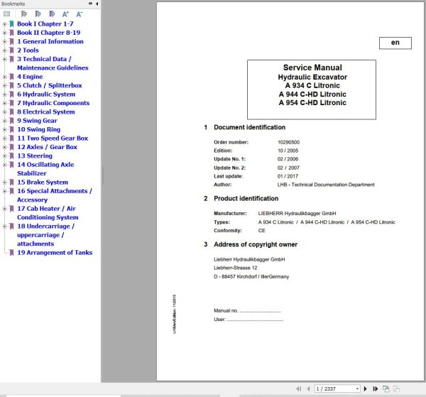
Liebherr Excavator A934C A944C-HD A954C-HD Litronic Service Manual 10290500
Size: 84.55 MB
Format: PDF
Language: English
Brand: Liebherr
Type of Machine: Excavator
Type of Manual: Service Manual, Electric and Hydraulic Diagrams
Model: Liebherr A934C Litronic, A944C-HD Litronic, A954C-HD Litronic Excavator
Engine: D 934 L 6A (Tier 3 – Stage III-A)
Order Number: 10290500
Publication Date: 2017
Number of Pages: 2337 Pages
100 USD
- Description
Description
Contents:
1 General Information
1.01 Standards and regulations
1.02 Changes and modifications to series
1.10 Safety instructions
1.21 Tightening torques for fittings
1.51 Fuels, lubricants and process chemicals
2 Tools
2.01 Special tools – general
2.02 Special tools for diesel engines
2.05 Special tools for hydraulic unit
2.06 Special tools for electrical equipment
2.07 Special tools for slewing gear mechanism
2.09 Special tools for axles (Kessler)
2.10 Stroke measuring device for control block
2.12 Assembly tools for hydraulic cylinders
2.13 Mounting device for piston rod bearings
2.14 Slotted nut wrench for slewing gear
2.15 Mounting device for multi-disc brake
2.20 Special tools, ERC cylinder
3 Technical Data / Maintenance Guidelines
3.05 Technical data A 934 C LI
3.06 Technical data A 934 C Li ERC
3.07 Technical data A 934 C HD LI
3.08 Technical data of A 934 C-HD LI ERC
3.09 Technical dataA 934 C HD LI Log Loader
3.11 Technical data
3.13 Technical data
3.15 Technical data
3.17 Inspection and maintenance schedule
3.18 Inspection and maintenance schedule
3.19 Inspection and maintenance schedule
3.20 Inspection and maintenance schedule
3.21 Inspection and maintenance schedule
3.23 Inspection and maintenance schedule
3.25 Inspection and maintenance schedule
3.27 Inspection and maintenance schedule
3.29 Lubrication schedule for A 934 C Litronic Type 1006
3.30 Lubricating chart for A 934 C Litronic ERC type 1418
3.31 Lubrication schedule for A 934 C-HD Litronic Type 1007
3.32 Lubricating chart for A 934 C Litronic ERC type 1419
3.33 Lubrication Schedule A 934 C-HD Litronic log loader Type 1053
3.35 Lubrication schedule for A 944 C-HD Litronic Type 194
3.37 Lubrication schedule A 944 C – HD Litronic log loader type 196
3.39 Lubrication schedule for A 954 C-HD Litronic Type 450
3.45 Adjustment protocol A 934 C Li
3.46 Adjustment protocol A 934 C LI
3.47 Adjustment protocol A 934 C LI ERC
3.50 Adjustment protocol A 934 C HD LI
3.51 Adjustment protocol A 934 C HD LI
3.52 Adjustment protocol A 934 C HD LI ERC
3.53 Adjustment protocol A 934 C HD LI log loader
3.55 Adjustment protocol A 944 C HD LI
3.56 Adjustment protocol A 944 C HD LI
3.57 Adjustment protocol A 944 C HD LI
3.60 Adjustment protocol A 944 C HD LI log loader
3.61 Adjustment protocol A 944 C HD LI log loader
3.62 Adjustment protocol A 944 C HD LI log loader
3.65 Adjustment protocol A 954 C HD LI
3.66 Adjustment protocol A 954 C HD LI
3.69 Adjustment guidelines for the hydraulic system
3.70 Checking and adjusting tasks V4.7
3.71 Adjustment guidelines for hydraulic system
3.73 Adjustment guidelines for hydraulic system
3.77 Adjustment guidelines for hydraulic system
3.80 Checking and adjusting tasks V4.8.1
4 Engine
4.05 Bleeding the fuel system
4.10 Technical data of diesel engine
4.12 Technical data of diesel engine
4.15 Technical data of diesel engine
4.20 Technical data of diesel engine
4.25 Liebherr diesel particle filter accessory kit
4.40 Datalogger version 2.3.00
4.41 Datalogger software version 2.3.09
5 Clutch / Splitterbox
5.10 Coupling
5.40 PVG 351 C pump distribution gear
6 Hydraulic System
6.50 Layout of hydraulic system type 1006/1007
6.55 Layout of hydraulic system type 194
6.60 Layout of hydraulic system type 450
6.70 Hydraulic schematic of working hydraulics type 1006/1007
6.71 Hydraulic schematic of working hydraulics type 1006/1007
6.72 Hydraulic schematic of working hydraulics type 1053 (log loader)
6.73 Hydraulic schematic of working hydraulics type 1053
6.75 Hydraulic diagram of working hydraulics
6.76 Hydraulic schematic of working hydraulics type 194
6.77 Hydraulic schematic of working hydraulics type 196 (log loader)
6.78 Hydraulic schematic of working hydraulics type 196
6.80 Hydraulic diagram of working hydraulics Typ 450
6.90 Hydraulic schematic of working hydraulics type 1418/1419
7 Hydraulic Components
7.05 Hydraulic pump removal, installation / Start-up
7.09 MKA 350 C 071 multiple circuit unit
7.11 Double variable-displacement pump DPVP 108
7.12 Double variable-displacement pump DPVP 108 in ERC models
7.13 LPV 165 variable-displacement pump
7.17 A4 VG variable-displacement pump
7.19 A10V028 ED variable-displacement pump
7.22 A6V regulating motor
7.25 FMF hydraulic fixed displacement motor
7.30 Hydraulic cylinder
7.33 Energy recuperation cylinder (ERC)
7.35 Hydraulic cylinder
7.42 Pilot control unit 1x (travelling foot pedal)
7.45 Control oil and regulation unit
7.50 Pilot control unit 4 x
7.54 Pilot control unit 2 x
7.56 Pilot control unit 2 x
7.60 M8 control valve block
7.62 M8 control valve block
7.64 M8 control valve block
7.70 Rotary connection 6 x
7.73 Rotary connection 7x
7.76 Rotary connection 9 x
7.81 Pilot-controlled primary pressure relief valve
7.83 Pilot-controlled pressure relief valve with additional pressure stage
7.85 Double stop valve for outrigger support
7.86 Pilot-controlled pressure relief valves with suction function
7.87 Secondary pressure relief valve, pilot-controlled
7.90 Suction valve
7.91 Restrictor check valve
7.93 Stop valves
8 Electrical System
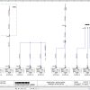
8.01 Overview of electrical symbols
8.02 Notes regarding the electrical system
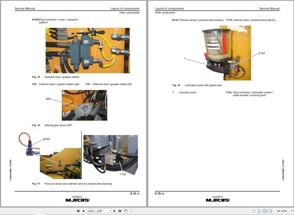
8.10 Layout of components
8.12 Electrical system in ERC models
8.25 Electrical system of basic machine A 934 C Li
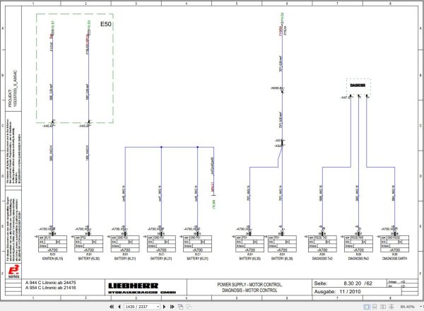
8.30 Electrical system of basic machine A 944 C Li / A 954 C Li
8.44 Operating symbols on the operator’s platform
8.50 BST excavator control (version 4…)
8.55 Monitoring display from version 4.8/V4.8.1
8.79 Control panel
8.80 Error code list
8.82 Slip ring contact
8.100 Electrical system – kits
8.101 Lifting boom when closing grapple
8.102 Travel alarm standard / LAM
8.103 Overload warning system
8.106 Industrial shutdown
8.107 Electr. stick cylinder shut-down/ potentiometer
8.108 Lift frame
8.108.5 Lift frame with lever switch
8.109 Turning grapple / LAM
8.110 Magnet system
8.111 Magnet system / LAM
8.112 Automatic central lubrication system
8.113 Back-up alarm
8.114 Quick change adapter
8.115 Additional beacon / Italy
8.116 Hydraulic trailer coupling
8.117 Joystick steering
8.118 Four-wheel steering
8.119 Travel drive summation
8.120 Steering changeover
8.122 Stick cylinder shut-down / electronic Hall sensor
9 Swing Gear
9.10 SAT slewing gear mechanism
9.20 Slewing gear brake / positioning brake
10 Swing Ring
10.10 Rotary connection
11 Two Speed Gear Box
11.10 2 HL 290 transmission
11.30 HBGV block for transmission
12 Axles / Gear Box
12.01 Tyres
12.03 Use of special tool (Kessler axles)
12.05 Introduction
12.07 Steering drive axle LT 71
12.08 Rigid axle D 71
12.16 Steering drive axle LT 81
12.18 Rigid axle D 81
12.25 Steering drive axle LT 81 for type 1053 (oscillating)
12.27 Steering drive axle LT 81 for type 1053 (rigid)
12.35 Steering drive axle LT 102
12.36 Rigid axle D 102
12.37 Differential D 108 for axles LT 102 / D102
12.50 D 51 auxiliary axle gear / spring pressure – multi disc brake
13 Steering
13.10 Hydraulic steering system, type 1006/1007
13.12 Hydraulic steering system, type 1053
13.14 Hydraulic steering system, type 196
13.16 Hydraulic steering system, type 194/450
13.18 Joystick steering
13.20 Steering valve
14 Oscillating Axle Stabilizer
14.10 Oscillating axle stabilization with automatic control
14.20 Support cylinder
14.22 Support cylinder
15 Brake System
15.05 Operating pressures of the brake system
15.08 Hydraulic brake system, type 1006/1007/1053
15.10 Hydraulic brake system, type 194/196
15.12 Hydraulic brake system type 450
15.20 Compact brake block
16 Special Attachments / Accessory
16.08 Pipe fracture safety valves boom cylinders
16.10 Pipe fracture safety system of boom cylinder
16.12 Pipe fracture safety valve of stick cylinder
16.14 Pipe fracture safety valve of stick cylinder with double check valve
16.16 Pipe-fracture safety valve of hoist cylinder
16.18 Pipe fracture safety valve of stick cylinder
16.70 Individual outrigger support control
16.78 Hydraulic operator’s cab elevation
16.80 Hydraulic operator’s cab elevation system
16.82 Stick cylinder shut-down with proximity switch
16.84 Electronic stick cylinder shut-down
16.85 Lifting booms when closing grapple
16.86 Generator drive accessory kit
16.88 Generator drive accessory kit
16.90 Generator conversion kit for LIKUFIX
16.95 Travel drive summation
17 Cab Heater / Air Conditioning System
17.40 Inspection and repair instructions for heating and air-conditioning system
17.50 Heating and air-conditioning system
18 Undercarriage / uppercarriage / attachments
18.01 Fixture of operator’s cab elevation system
18.50 Repair instructions for lubrication hoses
19 Arrangement of Tanks
Related Products
-
Liebherr Mining Excavators 84.88Gb PDF Updated 01.2022 Service Manuals DVD
USDLiebherr Mining Excavators 84.88Gb PDF Updated 01.2022 Service Manuals DVDSize: 84.88 Gb (PDF Files)Type of vehicle: Mining ExcavatorsType of manual: Service ManualLanguage: EnglishBrand: LiebherrFormat: PDFUpdate: 01.2022OS: All WindowsAmount of DVD: 1 DVDREALEASE :
01.13.2022
-
Liebherr Wheel Loader Updated 03.2022 Full Service Manuals DVD PDF
Original price was: 700.340Current price is: 340. USDLiebherr Wheel Loader 24.29GB Updated 03.2022 Full Service Manuals DVD PDFSize: 24.29 GB (PDF Files)Type of Vehicle: Wheel LoadersType of Document: Service ManualsFormat: PDFLanguage: EN, ZH, DEBrand: LiebherrDate Updated: 03.2022OS: All Windows 32 & 64 bitHigh-Speed Link DownloadDETAIL CONTENTS: “CLICK HERE“Hot-51%
REALEASE :
02.03.2022
REALEASE :
02.03.2022
-
Liebherr Crane LTM 1800 Service Manual Operators Manual Schematic
Original price was: 300.180Current price is: 180. USDThey are PDF Service Manual Operators Manual Schematic Manual, You need to use these to repair your vehicle.Hot-40%
REALEASE :
16.09.2022
REALEASE :
16.09.2022
-
Liebherr Crane HS HSG Operating Manual Spare Parts List Technical Information PDF DVD
Original price was: 1,500.540Current price is: 540. USDLiebherr Crane HS HSG Operating Manual Spare Parts Catalogue Technical Information DVD Size: 2.17 GB Fomat: PDF Language: EN,DE Brand: Liebherr Type of machine: Liebherr Crawler Crane Window: All Win 32 and 64 Bit, Mac OS Type of document: Liebherr Crane HS Operating Manual Liebherr Crane HS Spare Parts Catalogue Liebherr Crane HS Technical information Liebherr Crane HS Electrical Circuit Diagram Liebherr Crane HS Hydraulic Circuit DiagramHot-64%
REALEASE :
04.07.2022
REALEASE :
04.07.2022
-
Liebherr Wheeled and Crawler Excavators Updated 03.2022 Service Manuals DVD PDF
Original price was: 800.340Current price is: 340. USDLiebherr Wheeled and Crawler Excavators 48.3GB Updated 03.2022 Service Manuals DVD PDFSize: 48.3 GB (PDF Files)Format: PDFLanguage: EN, DEBrand: LiebherrDate Updated: 03.2022OS: All Windows 32 & 64bitType of Vehicle: Wheeled and Crawler ExcavatorsType of Document: Service ManualsHigh-Speed Link Download DETAIL CONTENTS: “CLICK HERE“Hot-58%
REALEASE :
02.03.2022
REALEASE :
02.03.2022
-
Liebherr Crawler Crane with Telescopic Boom LTR 1100 100 Ton Operator Manual Diagnostics LICCON Wiring Diagram
Original price was: 400.160Current price is: 160. USDLiebherr Crawler Crane with Telescopic Boom LTR 1100 100 Ton Operator Manual, Diagnostics LICCON & Wiring Diagram Size: 734 Mb Language: English_EN Format: PDF Model: LTR 1100 Capacity: 100 Ton SN: Z97542 Diesel Engine: D944 A7 DETAIL CONTENTS: “CLICK HERE“Hot-60%
REALEASE :
23.03.2022
REALEASE :
23.03.2022
-
Liebherr Mobile Crawler Cranes PDF Spare Parts List DVD
Original price was: 200.140Current price is: 140. USDLiebherr Mobile & Crawler Cranes 1.24 GB PDF Spare Parts Catalog DVDSize: 1.24 GBFormat: PDF, winrarBrand: LiebherrLanguages: English, Deutsch, Spanish, Russian, French, PortugueseType of Machine: Mobile Crane, Crawler Crane, Rough Terrain Crane, Tower CraneType of Document: Spare Parts CatalogsNumber of DVD: 1 DVDOS: Windows Vista, XP, 7, 8.1, 8, 10, MacOSHigh-Speed DownloadDETAIL CONTENTS: “CLICK HERE“Hot-30%
REALEASE :
29.03.2022
REALEASE :
29.03.2022
-
LIEBHERR LTM 1095-5.1 95 Ton Operator Manual Diagnostics LICCON Wiring Schematic PDF
Original price was: 200.60Current price is: 60. USDLIEBHERR LTM 1095-5.1 95 Ton Operator Manual, Diagnostics LICCON & Wiring DiagramSize: 77.3 MBFormat: PDFlanguage: EnglishBrand: LiebherrType of machine: Mobile CraneType of document:Model: LIEBHERR LTM 1095-5.1DETAIL CONTENTS: “CLICK HERE“Hot-70%
REALEASE :
25.03.2022
REALEASE :
25.03.2022
