
0 ITEMSVIEW CART


✓
Expert Support
✓
Full Speed
✓
100% Working
Liebherr Excavator LH 150 Service Manual 11837681
Size: 179.72 MB
Format: PDF
Language: English
Brand: Liebherr
Type of Machine: Excavator
Type of Manual: Service Manual, Electric and Hydraulic Diagrams
Model: Liebherr LH 150 Excavator
Types: LH 120 ET 1671, LH 150 CPG 1229, LH 150 ECG 1229,LH 150 ECHR 1229,
LH 150 ECPG 1229, LH 150 ET 1683,LH 150 ETG 1683
Order Number: 11837681
Publication Date: 2022
Number of Pages: 3805 Pages
150 USD
- Description
Description
Contents:
1 Safety
1.1 Description of staff
1.2 Intended use
1.3 Protective measures for staff
1.4 Protective devices on the machine
1.5 Emergency equipment on the machine
1.6 Safe operation
1.7 Safe work
1.8 Safe maintenance
1.9 Modifications to the machine
010 Introduction
010.1 Innovations and changes
010.008 Component documentation
010.030 Standards and regulations
010.043 Installation instructions: Mounting clamping nuts
010.050 Special tools, general
010.051 Special tools for hydraulic system
010.052 Special tools for electrical equipment
010.060 Special tools, ERC cylinder
010.070 Prescriptions de conservation
010.071 Conservation of hydraulic cylinders
020 Technical data
020.001 Technical data
030 Maintenance
030.001 Maintenance
030.051 Adjustment checklist LH150 EC
030.052 Adjustment checklist LH150 ETG
030.070 Check and adjustment tasks for LH 120 ETG
030.100 Preparations
030.105 Machine-specific data
030.110 Electric motor
030.115 Operating conditions
030.120 Servo control
030.125 Variable-displacement pump P1 to variable-displacement pump P4
030.130 Primary pressure relief valve
030.141 Control block, secondary pressures
030.142 Control block, secondary pressures
030.150 Slewing gear function
030.155 Hydraulic fan drive, fan circuit 2
030.161 Travel function
030.180 Medium pressure circuit
030.185 Turning grapple
030.190 Cab control triple joint
030.195 Generator drive
030.200 ERC cylinder
040 Drive group
040.020 Auxiliary drive, three-phase asynchronous motor
040.021 Auxiliary drive, three-phase asynchronous motor
040.055 Coupling
040.060 Pump distributor gear PVG 450 D
050 Cooling system
050.010 Cooling units
050.022 Fan drive
050.030 Reversible fan drive
060 Working hydraulics
060.001 Overview of hydraulic symbols
060.002 Colour code of hydraulic schematics
060.003 Reducing pressure in the hydraulic system
060.020 Design of uppercarriage hydraulic system
060.040 Design of hydraulic system of undercarriage
060.045 Design of hydraulic system of MCR undercarriage
060.046 Hydraulic schematics
070 Travel hydraulics
070.025 FMV travel motor
070.026 Travel brake valve for travel motor FMV
080 Hydraulic components
080.015 Hydraulic tank
080.020 Variable-displacement pump DPVO 165
080.025 Slewing gear pump DPVG 250
080.030 Fan pump A10VO
080.032 A11VO variable-displacement pump
080.040 Control oil unit
080.050 Control block positive control / boom block
080.051 Control block positive control / stick block
080.060 FMF slewing motor
080.075 Rotary connection 6x
080.076 Rotary connection 5x
080.080 Hydraulic differential cylinder
080.085 Energy recuperation cylinder (ERC)
080.086 ERC expansion tank
080.087 ERC piston rod protection
080.090 Accumulator
080.100 Line break safety valve
110 Electrical system
110.001 Overview of electrical symbols
110.002 Circuit diagrams in LIDOS
110.004 Certified electrician work area
110.005 Overview of ground points
110.020 Electrical system: uppercarriage
110.024 Electrical system: undercarriage
110.140 Electrical components adjustment procedures
110.050 Electrical schematics: Operator’s platform
110.050 Electrical schematics: LH 120 ET 1671
110.050 Electrical schematics: LH 150 ET 1683
110.050 Electrical schematics: LH 150 ETG 1683
110.050 Electrical schematics: LH 150 ECPG 1229
110.050 Electrical schematics: LH 150 ECHR 1229
110.050 Electrical schematics: LH 150 ECG 1229
110.050 Electrical schematics: LH 150 CPG 1229
110.200 Pilot control unit / joystick
120 Transmission/travel gearbox
120.010 Travel gearbox FAT 550
120.020 Travel brake
130 Axles/travel gear
130.050 Travel gear
130.055 Technical data and tightening torques
130.060 Checking travel gear components for wear
130.065 Wear limits of travel gear components
130.070 Chain
130.080 Idler
130.085 Track roller
130.090 Carrier roller
130.095 Slip ring seal
140 Steel parts of the basic machine
140.010 Repair welding guideline
150 Working attachment
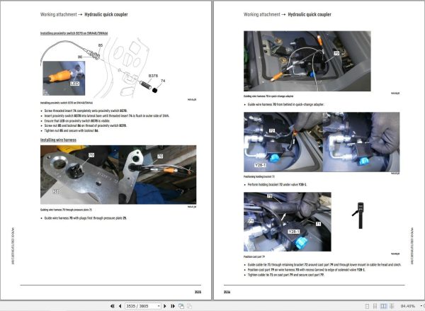
150.040 Hydraulic quick coupler
150.041 Hydraulic quick coupler, industrial stick
160 Operator’s cab, heating and air conditioning
160.001 Installation instruction for air-conditioning hose fittings
160.002 Mounting of operator’s cab elevation
160.010 Height adjustable operator’s cab
160.030 Stationary air conditioner
160.040 Air conditioning system
160.045 Air conditioning diagnosis / service
170 Lubrication system
170.005 Automatic central lubrication system
170.015 Central lubrication pump
170.050 Undercarriage lubricating pump
180 Slewing gearbox and slewing ring
180.001 Slewing ring
180.010 Slewing gearbox SAT 450
180.020 Slewing brake
190 Equipment and options
190.001 LiDAT remote diagnosis system
190.002 LiDAT: checking connection status
190.004 LiDAT remote diagnosis system (LiTU03)
190.005 LiDAT: creating a report and snapshot
190.030 Hydraulic oil pre-heating
190.055 Bypass filter
190.060 Control unit for pre-heating
190.090 Camera monitoring system
190.120 Extension to central lubrication system working tools
190.150 Watering device
200 Diagnosis
200.005 Sculi variables editor
200.006 Sculi access to the variables
200.020 Software update
200.030 Master 4: Reset on master module
200.035 CAN module addressing
200.036 Master 4: Master module
200.038 CAN connections
200.090 Troubleshooting
200.095 Information menu
200.098 Master 5: Master module (central control)
200.100 Master 5: Reset to factory settings
200.102 Master 5: Connect LiFT function
200.104 Master 5: Software update
200.106 Master 5: Connect SCULi diagnostic software
200.108 Master 5: Service file
200.110 Master 5: Import license file
200.112 Master 5: Software backup
200.114 Master 5: Data backup event
Related Products
-
Liebherr Mining Excavators 84.88Gb PDF Updated 01.2022 Service Manuals DVD
USDLiebherr Mining Excavators 84.88Gb PDF Updated 01.2022 Service Manuals DVDSize: 84.88 Gb (PDF Files)Type of vehicle: Mining ExcavatorsType of manual: Service ManualLanguage: EnglishBrand: LiebherrFormat: PDFUpdate: 01.2022OS: All WindowsAmount of DVD: 1 DVDREALEASE :
01.13.2022
-
Liebherr Crane HS HSG Operating Manual Spare Parts List Technical Information PDF DVD
Original price was: 1,500.540Current price is: 540. USDLiebherr Crane HS HSG Operating Manual Spare Parts Catalogue Technical Information DVD Size: 2.17 GB Fomat: PDF Language: EN,DE Brand: Liebherr Type of machine: Liebherr Crawler Crane Window: All Win 32 and 64 Bit, Mac OS Type of document: Liebherr Crane HS Operating Manual Liebherr Crane HS Spare Parts Catalogue Liebherr Crane HS Technical information Liebherr Crane HS Electrical Circuit Diagram Liebherr Crane HS Hydraulic Circuit DiagramHot-64%
REALEASE :
04.07.2022
REALEASE :
04.07.2022
-
Liebherr Mobile Crawler Cranes PDF Spare Parts List DVD
Original price was: 200.140Current price is: 140. USDLiebherr Mobile & Crawler Cranes 1.24 GB PDF Spare Parts Catalog DVDSize: 1.24 GBFormat: PDF, winrarBrand: LiebherrLanguages: English, Deutsch, Spanish, Russian, French, PortugueseType of Machine: Mobile Crane, Crawler Crane, Rough Terrain Crane, Tower CraneType of Document: Spare Parts CatalogsNumber of DVD: 1 DVDOS: Windows Vista, XP, 7, 8.1, 8, 10, MacOSHigh-Speed DownloadDETAIL CONTENTS: “CLICK HERE“Hot-30%
REALEASE :
29.03.2022
REALEASE :
29.03.2022
-
Liebherr Crane LTM 1800 Service Manual Operators Manual Schematic
Original price was: 300.180Current price is: 180. USDThey are PDF Service Manual Operators Manual Schematic Manual, You need to use these to repair your vehicle.Hot-40%
REALEASE :
16.09.2022
REALEASE :
16.09.2022
-
LIEBHERR LTM 1095-5.1 95 Ton Operator Manual Diagnostics LICCON Wiring Schematic PDF
Original price was: 200.60Current price is: 60. USDLIEBHERR LTM 1095-5.1 95 Ton Operator Manual, Diagnostics LICCON & Wiring DiagramSize: 77.3 MBFormat: PDFlanguage: EnglishBrand: LiebherrType of machine: Mobile CraneType of document:Model: LIEBHERR LTM 1095-5.1DETAIL CONTENTS: “CLICK HERE“Hot-70%
REALEASE :
25.03.2022
REALEASE :
25.03.2022
-
Liebherr Wheeled and Crawler Excavators Updated 03.2022 Service Manuals DVD PDF
Original price was: 800.340Current price is: 340. USDLiebherr Wheeled and Crawler Excavators 48.3GB Updated 03.2022 Service Manuals DVD PDFSize: 48.3 GB (PDF Files)Format: PDFLanguage: EN, DEBrand: LiebherrDate Updated: 03.2022OS: All Windows 32 & 64bitType of Vehicle: Wheeled and Crawler ExcavatorsType of Document: Service ManualsHigh-Speed Link Download DETAIL CONTENTS: “CLICK HERE“Hot-58%
REALEASE :
02.03.2022
REALEASE :
02.03.2022
-
Liebherr Crawler Crane with Telescopic Boom LTR 1100 100 Ton Operator Manual Diagnostics LICCON Wiring Diagram
Original price was: 400.160Current price is: 160. USDLiebherr Crawler Crane with Telescopic Boom LTR 1100 100 Ton Operator Manual, Diagnostics LICCON & Wiring Diagram Size: 734 Mb Language: English_EN Format: PDF Model: LTR 1100 Capacity: 100 Ton SN: Z97542 Diesel Engine: D944 A7 DETAIL CONTENTS: “CLICK HERE“Hot-60%
REALEASE :
23.03.2022
REALEASE :
23.03.2022
-
Liebherr Wheel Loader Updated 03.2022 Full Service Manuals DVD PDF
Original price was: 700.340Current price is: 340. USDLiebherr Wheel Loader 24.29GB Updated 03.2022 Full Service Manuals DVD PDFSize: 24.29 GB (PDF Files)Type of Vehicle: Wheel LoadersType of Document: Service ManualsFormat: PDFLanguage: EN, ZH, DEBrand: LiebherrDate Updated: 03.2022OS: All Windows 32 & 64 bitHigh-Speed Link DownloadDETAIL CONTENTS: “CLICK HERE“Hot-51%
REALEASE :
02.03.2022
REALEASE :
02.03.2022
