
1 ITEMVIEW CART

Total: 10.00

Expert Support
Full Speed
100% Working
100 USD
Contents:
010 Introduction
010.005 Standards and regulations
010.008 Component documentation
010.010 New features and changes
010.020 Safety instructions
010.043 Installation instructions: Mounting clamping nuts
010.050 Special tools, general
010.051 Special tools for hydraulic system
010.052 Special tools for electrical equipment
010.060 Special tools, ERC cylinder
010.070 Prescriptions de conservation
010.071 Conservation of hydraulic cylinders
010.072 Conservation guidelines for the SCR system
020 Technical data
020.001 Technical data
030 Maintenance
030.001 Maintenance
030.030 Emergency operations
030.050 Adjustment checklist LH150 M
030.051 Adjustment checklist LH150 C
030.100 Preparations
030.105 Machine-specific data
030.110 Diesel engine
030.115 Operating conditions
030.120 Servo control
030.125 Variable-displacement pump P1 to variable- displacement pump P4
030.130 Primary pressure relief valve
030.135 Powertest
030.140 Control block, secondary pressures
030.141 Control block, secondary pressures
030.150 Slewing gear function
030.155 Hydraulic fan drive, fan circuit 1 and 2
030.160 Undercarriage steering system
030.161 Travel function
030.180 Medium pressure circuit
030.185 Turning grapple
030.190 Cab control triple joint
030.195 Generator drive
030.200 ERC cylinder
040 Drive group
040.020 Technical data, diesel engine
040.022 Air filter system
040.025 SCR exhaust gas treatment system
040.030 Liebherr diesel engine D9508 A7
040.035 Diesel exhaust fluid system
040.040 Fuel system
040.050 SCRF exhaust treatment system
040.055 Coupling
040.060 Pump distributor gear PVG 450 D
050 Cooling system
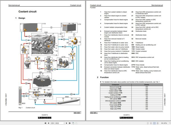
050.005 Coolant circuit
050.010 Cooling unit
050.022 Fan drive
050.030 Reversible fan drive
060 Working hydraulics
060.001 Overview of hydraulic symbols
060.002 Colour code of hydraulic schematics
060.003 Reducing pressure in the hydraulic system
060.020 Design of uppercarriage hydraulic system
060.030 Design of hydraulic system, wheeled undercarriage
060.040 Design of hydraulic system, crawler undercarriage
060.050 Hydraulic schematic LH150 M
12411110-002-HYD-00-DE.pdf
060.070 Hydraulic schematic LH150 C
12500963-100-HYD-00-DE.pdf
060.200 Hydraulic schematic / turning grapple
9644040-002-HYD-00-DE_1.pdf
060.205 Hydraulic schematic of standard fan drive
9644073-002-HYD-00-DE.pdf
060.210 Hydraulic schematic of reversible fan drive
9644071-002-HYD-00-DE.pdf
060.215 Hydraulic schematic of generator drive
9644058-001-HYD-00-DE.pdf
060.220 Hydraulic schematic: generator drive for Likufix
12462380-000-HYD-00-DE.pdf
060.225 Hydraulic schematic of grapple pressure reduction
94025183-002-HYD-00-DE_1.pdf
070 Travel hydraulics
070.020 CMVE travel motor
070.025 FMV travel motor
070.026 Travel brake valve for travel motor FMV
080 Hydraulic components
080.015 Hydraulic tank
080.020 Variable-displacement pump DPVO 165
080.025 Slewing gear pump DPVG 250
080.030 Fan pump A10VO
080.032 A11VO variable-displacement pump
080.040 Control oil unit
080.050 Control block positive control / boom block
080.051 Control block positive control / stick block
080.060 FMF slewing motor
080.075 Rotary connection 6x
080.076 Rotary connection 5x
080.080 Hydraulic differential cylinder
080.085 Energy recuperation cylinder (ERC)
080.086 ERC expansion tank
080.087 ERC piston rod protection
080.090 Accumulator
080.100 Line break safety valve
090 Steering system
090.010 Steering system
100 Brake system
100.010 Service brake
100.020 Parking brake
110 Electrical system
110.001 Overview of electrical symbols
110.002 Circuit diagrams in LIDOS
110.005 Overview of ground points
110.020 Electrical system: Operator’s platform
110.025 Electrical system: Fuses and relays
110.030 Electrical system: uppercarriage
110.050 Electrical system – operator workplace
94073059-003-DWG-00-EN.pdf
110.051 Electrical system – operator workplace
12497450-100-DWG-00-EN.pdf
110.060 Electrical system – uppercarriage
94067100-001-DWG-00-EN.pdf
110.061 Electrical system – uppercarriage
12558155-100-DWG-00-EN.pdf
110.070 Electrical system – undercarriage
94028865-001-DWG-00-EN.pdf
110.080 Electrical system, mobile undercarriage
94048420-003-DWG-00-EN.pdf
110.090 Circuit diagram: diesel engine
110.100 Circuit diagram: preheating
94087527-001-DWG-00-EN.pdf
110.200 Pilot control unit / joystick
120 Transmission / travel gearbox
120.010 Travel gearbox FAT 550
120.020 Travel brake
130 Axles / Drive
130.001 Tyres
130.010 Wheel sets
130.012 Wheel set programming (axle alignment)
130.015 Levelling of wheel sets
130.020 Driven oscillating axle D104
130.025 Non-driven oscillating axle S71
130.050 Travel gear
130.055 Technical data and tightening torques
130.060 Checking travel gear components for wear
130.065 Wear limits of travel gear components
130.070 Chain
130.075 Tensioning unit
130.080 Idler
130.085 Track roller
130.090 Carrier roller
130.095 Slip ring seal
140 Steel components – basic machine
140.010 Repair welding guideline
140.012 Supports / folding arms
140.015 Supports / support cylinders
150 Working equipment
150.040 Hydraulic quick coupler
150.041 Hydraulic quick coupler, industrial stick
160 Operator’s cab / heating / air-conditioning unit
160.001 Installation instruction for air-conditioning hose fittings
160.002 Mounting of operator’s cab elevation
160.010 Height adjustable operator’s cab
160.030 Auxiliary heater
160.035 Heating and air conditioning unit
160.040 Heating and air conditioning system
160.045 Air conditioning diagnosis / service
170 Lubrication system
170.001 Repair of lubrication hose
170.005 Automatic central lubrication system
170.015 Central lubrication pump
170.025 Progressive distributor
170.050 Undercarriage lubricating pump
180 Slewing gear mechanism / Slewing ring
180.001 Slewing ring
180.010 Slewing gearbox SAT 450
180.020 Slewing brake
190 Equipment / Options
190.001 LiDAT remote diagnosis system
190.002 LiDAT: checking connection status
190.004 LiDAT remote diagnosis system (LiTU03)
190.005 LiDAT: creating a report and snapshot
190.010 Engine oil pre-heating
190.020 Coolant pre-heating
190.030 Hydraulic oil pre-heating
190.035 Generator drive accessory kit
190.040 Fuel preheating
190.055 Bypass filter
190.060 Control unit for pre-heating
190.090 Camera monitoring system
190.120 Extension to central lubrication system working tools
190.150 Watering device
200 Diagnosis
200.005 Sculi variables editor
200.006 Sculi – access to the variables
200.012 Accelerating starting time from Sculi Wizard
200.016 SCR system check
200.020 Software update
200.030 Master 4: Reset on master module
200.035 CAN module addressing
200.036 Master 4: Master module
200.038 CAN connections
200.090 Troubleshooting
200.095 Information menu
200.098 Master 5: Master module (central control)
200.100 Master 5: Reset to factory settings
200.102 Master 5: Connect “LiFT” function
200.104 Master 5: Software update
200.106 Master 5: Connect SCULi diagnostic software
200.108 Master 5: Service file
200.110 Master 5: Import license file
200.112 Master 5: Software backup
200.114 Master 5: Data backup event

REALEASE :
02.03.2022
REALEASE :
02.03.2022
REALEASE :
01.13.2022

REALEASE :
25.03.2022
REALEASE :
25.03.2022

REALEASE :
16.09.2022
REALEASE :
16.09.2022

REALEASE :
29.03.2022
REALEASE :
29.03.2022

REALEASE :
02.03.2022
REALEASE :
02.03.2022

REALEASE :
04.07.2022
REALEASE :
04.07.2022

REALEASE :
23.03.2022
REALEASE :
23.03.2022
 Automotive - Heavy Equipment - Truck & Bus - Forklift - Crane