
1 ITEMVIEW CART

Total: 10.00
Expert Support
Full Speed
100% Working
100 USD
Contents:
1 General
1.01 Standards and regulations
1.02 Modifications of series
1.10 Safety instructions
1.11 Safety instructions
1.21 Tightening torques for fittings
1.40 Filling quantities
1.51 Fuels, lubricants and process chemicals
1.55 TE_ML05 lubricant list
1.56 TE_ML07 lubricant list
1.60 Conservation guidelines
2 Tools
2.01 Special tools – general
2.02 Special tools for diesel engines
2.03 Special tools for ZW equipment
2.05 Special tools for hydraulic system
2.06 Special tools for electrical equipment
2.07 Special tools for gears
2.08 Special tools for axles (ZF)
2.09 Special tools for axles (Kessler)
2.12 Assembly tools for hydraulic cylinders
2.13 Mounting device for piston rod bearings
2.14 Slotted nut wrench for slewing gear mechanism
2.15 Mounting device for multi-disk brake
3 Technical data / Maintenance instructions
3.05 Type overview of A 900 C ZW Litronic F.D.
3.14 Technical data
3.25 Inspection and maintenance schedule
3.37 Adjustment of ZW rail gear
3.38 Adjusting the proximity switches at the rail gear
3.45 Adjustment protocol type 1033
3.46 Adjustment protocol type 1384/1385
3.47 Checking and adjusting tasks
3.60 Warning and information signs on A 900 C ZW
4 Drive motor
4.05 Bleeding the fuel system
4.12 Technical data of diesel engines
4.25 Installation and check list
4.27 Liebherr diesel particle filter accessory kit
4.40 Datalogger version 2.3.00
4.41 Datalogger software version 2.3.09
5 Coupling / Pump distribution gear
5.10 Coupling
5.20 Pump distributor gear
6 Hydraulic system
6.01 LSC system
6.31 Layout of hydraulic system
6.45 Hydraulic system A 900 C ZW EDC 37728
6.46 Hydraulic system A 900 C ZW F.D. 53810
6.61 Function of ZW rail gear
7 Hydraulic components
7.01 Hydraulic pumps – dismantling, installation and initial operation
7.05 Variable-displacement pump DPVP 108
7.10 Variable-displacement pump A10V0
7.20 FMF hydraulic fixed displacement motor
7.27 DMVA regulating motor (travel drive)
7.28 DMVA regulating motor (travel drive)
7.30 Hydraulic cylinder
7.31 Extension and retraction times of hydraulic cylinders
7.32 Hydraulic double plunger cylinder
7.41 Control oil and regulating unit
7.49 Pilot control unit 4x
7.51 Control block LSC
7.68 Leak oil check at control valve blocks
7.70 Rotary connection 6 x
7.75 Rotary connection 7x
7.81 Axle control block of the rail guide
7.95 Accumulator
8 Electrical system
8.01 Overview of electrical symbols
8.02 Notes regarding the electrical system
8.12 Arrangement of components
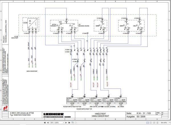
8.34 Electical system with installation kits and wiring harnesses
8.36 Electical system with installation kits and wiring harnesses
8.38 Electical system with installation kits and wiring harnesses
8.44 Operating symbols on the operator’s platform
8.50 Data logger
8.52 Operator ID code
8.60 Electronically controlled working and travelling pedal
8.62 Calibration of the electric foot pedals
8.70 ZW monitoring display (TDS01)
8.72 Monitoring display from V.4.7.2
8.79 Control panel
8.80 Error code list
8.81 Emergency actuation (emergency operation)
8.82 Slip ring rotary connection
8.90 Resistance measurement
9 Slewing gear mechanism
9.10 Slewing gear mechanism
9.21 Slewing gear brake
9.25 Positioning slewing brake
10 Slewing ring
10.10 Slewing ring
11 Transmission
11.12 2 HL 290 transmission
11.35 HBGV block for transmission 2 HL 290
12 Axel / Rail guide system
12.35 Tyres
12.41 ZW rail gear
12.50 MS-E 3070 steering axle
12.52 MT-E 3070 rigid axle
12.54 MS/MT-E 3070 input unit and differential
12.90 Measuring of the wheel flange of the rail chassis
12.91 Measuring of tyre track width
12.95 Wear limits
13 Steering
13.01 Locking of steering in friction wheel rail chassis
13.10 Hydraulic steering system
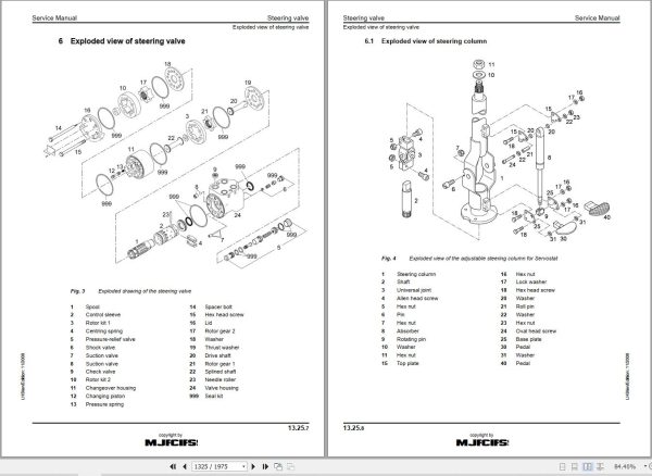
13.25 Steering valve
13.33 Steering cylinder
14 Oscillating axle support
14.15 Oscillating axle support with automatic control
14.16 Oscillating axle support with automatic control
14.20 Support cylinder
15 Brake system / Air pressure system
15.05 Operating pressures of the brake system
15.10 Hydraulic brake system
15.20 Compact brake block
15.30 Rail wheel brake
15.54 Single-circuit pneumatic railcar brake system
15.55 Two-circuit pneumatic railcar brake system
15.56 Hydraulic railcar brake system
16 Special equipment / Accessory kits
16.01 Pipe fracture safety valve for hoist cylinder
16.02 Pipe fracture safety valve for stick cylinder
16.03 Pipe fracture safety valve for boom cylinders
16.10 Optional equipment control
16.11 Terminal assignment of attachments
16.12 Changeover bucket – closing cylinder
16.13 LIEBHERR hydro magnet
16.14 Camera monitoring system
16.15 Hydraulic quick-change adapter
16.18 LIKUFIX hydraulic coupling system
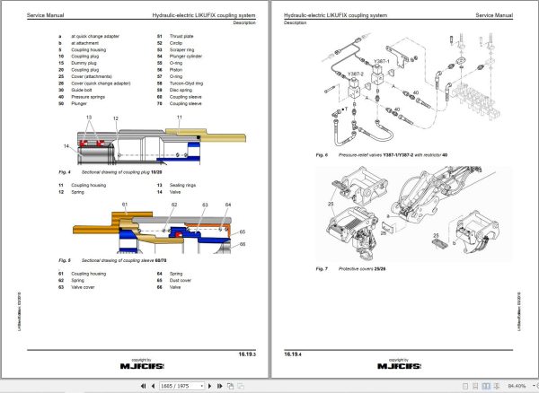
16.19 Hydraulic-electric LIKUFIX coupling system
16.21 Pressure and flow reduction
16.22 Hydraulic hammer
16.24 Swivel rotator TR-20/TR-25
16.40 Accessory kit AS1
16.49 Mechanical/hydraulic stroke limitation
16.50 Overload shut-down system with stroke and boom limitation
16.51 Overload shut-down system with stroke and boom limitation
16.52 Adjustment of the stroke and boom limitation parameters
16.53 Overload shut-down system for lateral adjustable boom
16.54 Inclination sensor
16.57 Emergency hydraulics
16.60 Refuelling pump
16.65 Bypass filter
16.69 LIEBHERR bypass filter
17 Operator’s cab / Heating and air-conditioning
17.30 Auxiliary heater
17.40 Inspection and repair instructions for heating and air-conditioning system
17.50 Heating and air-conditioning system
18 Rail roader installations / Attachments
18.50 Repair instructions for lubrication hoses
18.51 Central lubrication system
170.015 Semi-automatic central lubrication system
18.54 Fully automatic central lubricating system
18.56 Central lubrication pump
18.58 SX-E progressive distributor
18.59 MX-F progressive distributor
19 Tank arrangement

REALEASE :
29.03.2022
REALEASE :
29.03.2022

REALEASE :
04.07.2022
REALEASE :
04.07.2022
REALEASE :
01.13.2022

REALEASE :
02.03.2022
REALEASE :
02.03.2022

REALEASE :
02.03.2022
REALEASE :
02.03.2022

REALEASE :
25.03.2022
REALEASE :
25.03.2022

REALEASE :
16.09.2022
REALEASE :
16.09.2022

REALEASE :
23.03.2022
REALEASE :
23.03.2022
 Automotive - Heavy Equipment - Truck & Bus - Forklift - Crane