
0 ITEMSVIEW CART

✓
Expert Support
✓
Full Speed
✓
100% Working
Liebherr Pipe Layers RL44 RL54 RL64 Service Manual
Size: 141.59 MB
Format: PDF
Language: English
Brand: Liebherr
Type of Machine: Pipe Layers
Type of Manual: Service Manual, Electric and Hydraulic Diagrams
Model: Liebherr RL44 RL54 RL64 Pipe Layers
Number of Pages: 1525 Pages
100 USD
- Description
Description
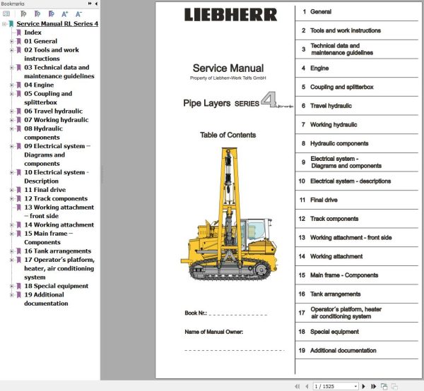
Contents:
01 General
Foreword and explanation
Safety regulations
Charts
Conservation guidelines
Material weights
02 Tools and work instructions
Special tools
Repair welding
Installation instructions
03 Technical data and maintenance guidelines
Technical data
Maintenance and inspection schedule
Maintenance and inspection instructions
Adjustment check list
Test and adjustment tasks
04 Engine
Data page
Fan and cylinder arrangement
05 Coupling and splitterbox
Data page
Coupling
Splitterbox
Coupling pump output
06 Travel hydraulic
Data page
Design
Function
Repair work and troubleshooting
Component arrangement
07 Working hydraulic
Data page
Design
Function
Repair work and troubleshooting
Component arrangement
08 Hydraulic components
Variable displacement pump
Variable displacement motor
Regulating pump – Working hydraulic / fan drive
Double gear pump – Replenishing / fan drive
Gear motor – fan drive
Axial piston fixed displacement motor – Fan drive
Pilot control – Working hydraulic
Control valve block
Valves
Hydraulic cylinder
Control motor – Hoist gear – winch
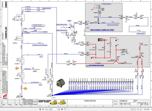
09 Electrical system – Diagrams and components
Circuit diagram, component description, function list
Instrument panel
Component arrangement
Travel joystick
Inching- / brake pedal
10 Electrical system – Description
Diagnostics Software LinDiag
Software PDL – Diesel particle filter
Service Code List
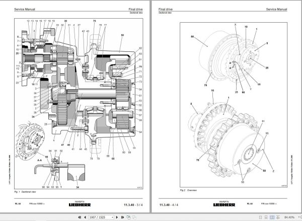
11 Final drive
Data page
Design and function
Sectional view – Final drive
12 Track components
Data page
Design, function, wear and evaluation
Inspection checklist / Wear chart
Track roller frame and idler unit
Track roller
Carrier roller
Tension unit
13 Working attachment – front side
14 Working attachment
Hoist gear
Rope winch
Putting the overload warning device into service
15 Main frame – Components
Cooler arrangement
Equalizer bar
Engine mount
16 Tank arrangements
Hydraulic tank
Fuel tank
Battery compartment
17 Operator’s platform, heater, air conditioning system
Operator’s platform
Heater with blower
Air conditioning system
Operator’s seat – Air cushioned
Throttle control
18 Special equipment
Refueling pump
Add-on installations – Pipe chamfering deviceand welding generator
19 Additional documentation
Schematics Travel hydraulic
Schematics Working hydraulic
Current Flow Diagrams
Related Products
-
Liebherr Mobile Crawler Cranes PDF Spare Parts List DVD
Original price was: 200.140Current price is: 140. USDLiebherr Mobile & Crawler Cranes 1.24 GB PDF Spare Parts Catalog DVDSize: 1.24 GBFormat: PDF, winrarBrand: LiebherrLanguages: English, Deutsch, Spanish, Russian, French, PortugueseType of Machine: Mobile Crane, Crawler Crane, Rough Terrain Crane, Tower CraneType of Document: Spare Parts CatalogsNumber of DVD: 1 DVDOS: Windows Vista, XP, 7, 8.1, 8, 10, MacOSHigh-Speed DownloadDETAIL CONTENTS: “CLICK HERE“Hot-30%
REALEASE :
29.03.2022
REALEASE :
29.03.2022
-
Liebherr Wheeled and Crawler Excavators Updated 03.2022 Service Manuals DVD PDF
Original price was: 800.340Current price is: 340. USDLiebherr Wheeled and Crawler Excavators 48.3GB Updated 03.2022 Service Manuals DVD PDFSize: 48.3 GB (PDF Files)Format: PDFLanguage: EN, DEBrand: LiebherrDate Updated: 03.2022OS: All Windows 32 & 64bitType of Vehicle: Wheeled and Crawler ExcavatorsType of Document: Service ManualsHigh-Speed Link Download DETAIL CONTENTS: “CLICK HERE“Hot-58%
REALEASE :
02.03.2022
REALEASE :
02.03.2022
-
Liebherr Crawler Crane with Telescopic Boom LTR 1100 100 Ton Operator Manual Diagnostics LICCON Wiring Diagram
Original price was: 400.160Current price is: 160. USDLiebherr Crawler Crane with Telescopic Boom LTR 1100 100 Ton Operator Manual, Diagnostics LICCON & Wiring Diagram Size: 734 Mb Language: English_EN Format: PDF Model: LTR 1100 Capacity: 100 Ton SN: Z97542 Diesel Engine: D944 A7 DETAIL CONTENTS: “CLICK HERE“Hot-60%
REALEASE :
23.03.2022
REALEASE :
23.03.2022
-
Liebherr Wheel Loader Updated 03.2022 Full Service Manuals DVD PDF
Original price was: 700.340Current price is: 340. USDLiebherr Wheel Loader 24.29GB Updated 03.2022 Full Service Manuals DVD PDFSize: 24.29 GB (PDF Files)Type of Vehicle: Wheel LoadersType of Document: Service ManualsFormat: PDFLanguage: EN, ZH, DEBrand: LiebherrDate Updated: 03.2022OS: All Windows 32 & 64 bitHigh-Speed Link DownloadDETAIL CONTENTS: “CLICK HERE“Hot-51%
REALEASE :
02.03.2022
REALEASE :
02.03.2022
-
LIEBHERR LTM 1095-5.1 95 Ton Operator Manual Diagnostics LICCON Wiring Schematic PDF
Original price was: 200.60Current price is: 60. USDLIEBHERR LTM 1095-5.1 95 Ton Operator Manual, Diagnostics LICCON & Wiring DiagramSize: 77.3 MBFormat: PDFlanguage: EnglishBrand: LiebherrType of machine: Mobile CraneType of document:Model: LIEBHERR LTM 1095-5.1DETAIL CONTENTS: “CLICK HERE“Hot-70%
REALEASE :
25.03.2022
REALEASE :
25.03.2022
-
Liebherr Mining Excavators 84.88Gb PDF Updated 01.2022 Service Manuals DVD
USDLiebherr Mining Excavators 84.88Gb PDF Updated 01.2022 Service Manuals DVDSize: 84.88 Gb (PDF Files)Type of vehicle: Mining ExcavatorsType of manual: Service ManualLanguage: EnglishBrand: LiebherrFormat: PDFUpdate: 01.2022OS: All WindowsAmount of DVD: 1 DVDREALEASE :
01.13.2022
-
Liebherr Crane LTM 1800 Service Manual Operators Manual Schematic
Original price was: 300.180Current price is: 180. USDThey are PDF Service Manual Operators Manual Schematic Manual, You need to use these to repair your vehicle.Hot-40%
REALEASE :
16.09.2022
REALEASE :
16.09.2022
-
Liebherr Crane HS HSG Operating Manual Spare Parts List Technical Information PDF DVD
Original price was: 1,500.540Current price is: 540. USDLiebherr Crane HS HSG Operating Manual Spare Parts Catalogue Technical Information DVD Size: 2.17 GB Fomat: PDF Language: EN,DE Brand: Liebherr Type of machine: Liebherr Crawler Crane Window: All Win 32 and 64 Bit, Mac OS Type of document: Liebherr Crane HS Operating Manual Liebherr Crane HS Spare Parts Catalogue Liebherr Crane HS Technical information Liebherr Crane HS Electrical Circuit Diagram Liebherr Crane HS Hydraulic Circuit DiagramHot-64%
REALEASE :
04.07.2022
REALEASE :
04.07.2022
