
0 ITEMSVIEW CART

✓
Expert Support
✓
Full Speed
✓
100% Working
Liebherr Pump Distribution Gears PVG 250B-351B Repair Manual 12494744
Size: 15.06 MB
Format: PDF
Language: English
Brand: Liebherr
Type of Machine: Pump Distribution Gears
Type of Manual: Repair Manual
Model: Liebherr PVG 250B, PVG 2501, PVG 250B, PVG 300B, PVG 350B, PVG 351B
Order Number: 12494744
Publication Date: 2017
Number of Pages: 110 Pages
20 USD
- Description
Description
Contents:
1 Symbols and safety instructions
1.1 Symbols in the Repair manual
1.1.1 Identification of operational safety instructions
1.1.2 Additional identifications
1.2 Safety instructions
1.2.1 General safety instructions
1.2.2 Changes to the hydraulic unit
1.2.3 Prevention of personal injuries
1.2.4 Prevention of property damage
1.2.5 Prevention of environmental damage
2 Tools
2.1 Customary tools T = Tool
2.2 Special tool LT = Liebherr tool
2.3 Instructions for the use of tools
3 Options
3.1 Validity
3.1.1 Pump distribution gears (type B2)
3.1.2 Pump distribution gears (type B4)
3.1.3 Pump distribution gears (type B6)
3.1.4 Pump distribution gears (type B7)
3.1.5 Pump distribution gears (type B9)
3.1.6 Pump distribution gears (type B10)
3.1.7 Pump distribution gears (type B11)
3.1.8 Pump distribution gears (type B13)
4 Sealing work
4.1 Overview
4.2 Sealing the drive shaft
4.2.1 Overview
4.2.2 Sealing the bearing cover
4.2.3 Sealing the cover
4.3 Sealing the output
4.3.1 Sealing the output, Option B2
4.3.2 Sealing the output, Option B4
4.3.3 Sealing the output, Option B6
4.3.4 Sealing the output, Option B7
4.3.5 Sealing the output, Option B9
4.3.6 Sealing the output, Option B10
4.3.7 Sealing the output, Option B11
4.3.8 Sealing the output, Option B13
4.4 Sealing the through drive
4.5 Sealing the oil dipstick
4.6 Sealing the oil drain plug
4.7 Sealing the ventilation and extraction filter
4.8 Sealing the intermediate drive
5 RK drive shaft
5.1 Overview
5.2 Removing the drive shaft bearing
5.3 Installing the drive shaft bearing
6 Output bearings
6.1 Overview
6.2 Intermediate drive bearing
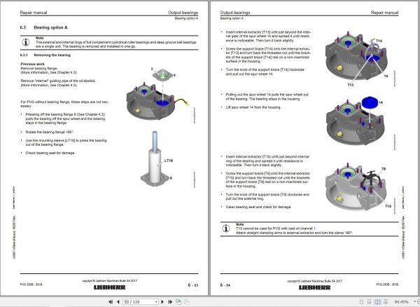
6.3 Bearing option A
6.3.1 Removing the bearing
6.3.2 Installing the bearing
6.4 Bearing Option B
6.4.1 Removing the bearing
6.4.2 Installing the bearing
6.5 Intermediate drive bearing
6.5.1 Overview
6.5.2 Removing the bearing
6.5.3 Installing the bearing
7 Gearbox test
7.1 Test bench
7.1.1 Prerequisites for the commissioning / the test on the test bench
7.1.2 Installation in the test bench
7.1.3 Settings
7.2 Commissioning / functional test after repair
7.2.1 Run-in phase / functional test
7.2.2 Test analysis
7.2.3 Test completion
8 Tightening torques
8.1 Standard torques for screw connections
8.2 Regulating pin torque
8.3 Hex nut torque Qmin. limit stop screw
8.4 Nozzle torque
8.5 Valve torque
8.5.1 Pressure feeder valve torque
8.5.2 Pressure limiting valve torque
8.5.3 Shuttle valve torque
8.5.4 Non-return valve torque
8.6 Torques for standard Vsl screw plugs
8.7 Torques for screw plugs tapered thread
8.8 Torques for screw plugs with o-ring
8.9 Torques for VSTI standard screw plugs
8.10 Torques for guide bush 1 without o-ring
8.11 Torques for guide bush 1 with o-ring (steel gasket version)
8.12 Torques for guide bush 1 with o-ring (gap seal version)
8.13 Pressure cut-off torques
8.13.1 Regulator pressure cut-off
8.13.2 Regulator pressure cut-off with oversteer
8.14 Brake valve torques
8.15 Hydraulic fluid drain torque
8.16 Screen torque
8.17 Torques for screw connections with cutting ring
8.18 Torque for screw connection, hinged threaded union, and Minimess (series L)
8.19 Incremental crosswise tightening procedure
8.19.1 Crosswise tightening procedure with four screws
8.19.2 Crosswise tightening procedure with more than four screws, odd number
8.19.3 Crosswise tightening procedure with 6 screws
8.19.4 Crosswise tightening procedure with more than six screws, even number
Related Products
-
Liebherr Wheeled and Crawler Excavators Updated 03.2022 Service Manuals DVD PDF
Original price was: 800.340Current price is: 340. USDLiebherr Wheeled and Crawler Excavators 48.3GB Updated 03.2022 Service Manuals DVD PDFSize: 48.3 GB (PDF Files)Format: PDFLanguage: EN, DEBrand: LiebherrDate Updated: 03.2022OS: All Windows 32 & 64bitType of Vehicle: Wheeled and Crawler ExcavatorsType of Document: Service ManualsHigh-Speed Link Download DETAIL CONTENTS: “CLICK HERE“Hot-58%
REALEASE :
02.03.2022
REALEASE :
02.03.2022
-
Liebherr Mining Excavators 84.88Gb PDF Updated 01.2022 Service Manuals DVD
USDLiebherr Mining Excavators 84.88Gb PDF Updated 01.2022 Service Manuals DVDSize: 84.88 Gb (PDF Files)Type of vehicle: Mining ExcavatorsType of manual: Service ManualLanguage: EnglishBrand: LiebherrFormat: PDFUpdate: 01.2022OS: All WindowsAmount of DVD: 1 DVDREALEASE :
01.13.2022
-
LIEBHERR LTM 1095-5.1 95 Ton Operator Manual Diagnostics LICCON Wiring Schematic PDF
Original price was: 200.60Current price is: 60. USDLIEBHERR LTM 1095-5.1 95 Ton Operator Manual, Diagnostics LICCON & Wiring DiagramSize: 77.3 MBFormat: PDFlanguage: EnglishBrand: LiebherrType of machine: Mobile CraneType of document:Model: LIEBHERR LTM 1095-5.1DETAIL CONTENTS: “CLICK HERE“Hot-70%
REALEASE :
25.03.2022
REALEASE :
25.03.2022
-
Liebherr Crane LTM 1800 Service Manual Operators Manual Schematic
Original price was: 300.180Current price is: 180. USDThey are PDF Service Manual Operators Manual Schematic Manual, You need to use these to repair your vehicle.Hot-40%
REALEASE :
16.09.2022
REALEASE :
16.09.2022
-
Liebherr Wheel Loader Updated 03.2022 Full Service Manuals DVD PDF
Original price was: 700.340Current price is: 340. USDLiebherr Wheel Loader 24.29GB Updated 03.2022 Full Service Manuals DVD PDFSize: 24.29 GB (PDF Files)Type of Vehicle: Wheel LoadersType of Document: Service ManualsFormat: PDFLanguage: EN, ZH, DEBrand: LiebherrDate Updated: 03.2022OS: All Windows 32 & 64 bitHigh-Speed Link DownloadDETAIL CONTENTS: “CLICK HERE“Hot-51%
REALEASE :
02.03.2022
REALEASE :
02.03.2022
-
Liebherr Crane HS HSG Operating Manual Spare Parts List Technical Information PDF DVD
Original price was: 1,500.540Current price is: 540. USDLiebherr Crane HS HSG Operating Manual Spare Parts Catalogue Technical Information DVD Size: 2.17 GB Fomat: PDF Language: EN,DE Brand: Liebherr Type of machine: Liebherr Crawler Crane Window: All Win 32 and 64 Bit, Mac OS Type of document: Liebherr Crane HS Operating Manual Liebherr Crane HS Spare Parts Catalogue Liebherr Crane HS Technical information Liebherr Crane HS Electrical Circuit Diagram Liebherr Crane HS Hydraulic Circuit DiagramHot-64%
REALEASE :
04.07.2022
REALEASE :
04.07.2022
-
Liebherr Mobile Crawler Cranes PDF Spare Parts List DVD
Original price was: 200.140Current price is: 140. USDLiebherr Mobile & Crawler Cranes 1.24 GB PDF Spare Parts Catalog DVDSize: 1.24 GBFormat: PDF, winrarBrand: LiebherrLanguages: English, Deutsch, Spanish, Russian, French, PortugueseType of Machine: Mobile Crane, Crawler Crane, Rough Terrain Crane, Tower CraneType of Document: Spare Parts CatalogsNumber of DVD: 1 DVDOS: Windows Vista, XP, 7, 8.1, 8, 10, MacOSHigh-Speed DownloadDETAIL CONTENTS: “CLICK HERE“Hot-30%
REALEASE :
29.03.2022
REALEASE :
29.03.2022
-
Liebherr Crawler Crane with Telescopic Boom LTR 1100 100 Ton Operator Manual Diagnostics LICCON Wiring Diagram
Original price was: 400.160Current price is: 160. USDLiebherr Crawler Crane with Telescopic Boom LTR 1100 100 Ton Operator Manual, Diagnostics LICCON & Wiring Diagram Size: 734 Mb Language: English_EN Format: PDF Model: LTR 1100 Capacity: 100 Ton SN: Z97542 Diesel Engine: D944 A7 DETAIL CONTENTS: “CLICK HERE“Hot-60%
REALEASE :
23.03.2022
REALEASE :
23.03.2022
