
8 ITEMSVIEW CART


Total: 175.00


Expert Support
Full Speed
100% Working
150 USD
Contents:
010 Introduction
010.1 Safety instructions
010.2 Special tools for maintenance and repair work
010.3 Standards and specifications
010.4 Conservation guidelines
010.5 Repair welding
010.6 Hydraulic symbols
010.7 Electrical symbols
010.8 Material weights
020 Technical data
020.1 Drive group
020.2 Cooling system
020.3 Working hydraulics
020.4 Travel hydraulics
020.5 Hydraulic components
020.6 Electrical system
020.7 Travel gear, axles, tyres, drive shafts
020.8 Steel components Basic machine
030 Maintenance
030.1 General information on the maintenance and inspection schedule
030.2 Maintenance and inspection schedule
030.3 Fill quantities and lubrication chart
030.4 Lubricants and fuels
030.5 Maintenance tasks
030.6 Adjustment checklist
030.7 Adjustment procedure
040 Drive group
040.1 Diesel engine
040.2 Clutch
050 Cooling system
050.1 Cooling system – Full overview
050.2 Cooling system – Full overview
050.3 Cooler arrangement
050.4 Hydraulic
060 Working hydraulics
060.1 Working hydraulics – Full overview
060.2 Working hydraulics – Full overview
060.3 Regulating pump
060.4 Proportional control valve block
060.5 Working hydraulic pilot control unit
060.6 Hydraulic cylinder
070 Travel hydraulics
070.1 Travel hydraulics – Full overview
070.2 Travel hydraulics – Full overview
070.3 Travel hydraulics axial piston variable displacement pump
070.4 Travel hydraulics axial piston variable displacement pump
070.5 Variable displacement motors
080 Hydraulic components
080.1 Hydraulic system – Full overview
080.2 Hydraulic system – Full overview
080.3 Hydraulic system – Full overview
080.4 Valves
080.5 Hydraulic tank
080.6 Line filter
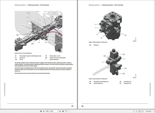
090 Steering system
090.1 Steering system – Full overview
090.2 Steering system – Full overview
090.3 Steering system Full overview
090.4 Priority valve
090.5 Steering aggregate
100 Brake system
100.1 Brake system – Full overview
100.2 Brake system – Full overview
100.3 Valve block
100.4 Pressure accumulator
100.5 Inching brake pedal
100.6 Multiple disk brake
110 Electrical system
110.1 Electrical system – Full overview
110.2 Lighting – Full overview
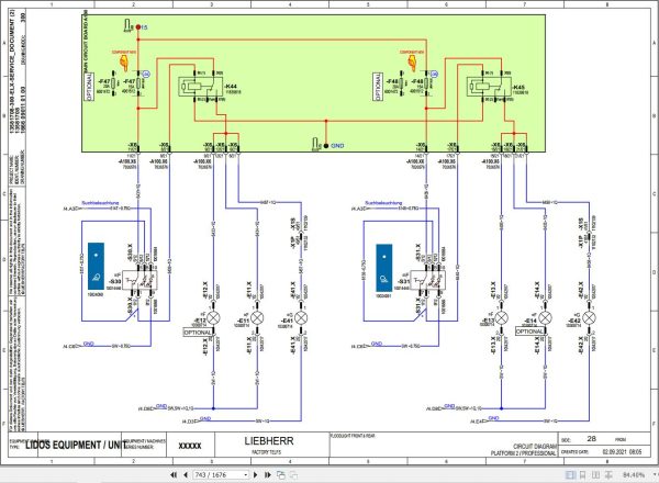
110.3 Circuit diagrams
110.4 Electrical components of operator’s cab
110.5 Electrical components of diesel engine – Full overview (emission stage III-A)
110.6 Electrical components of diesel engine – Full overview
110.7 Electrical components of diesel engine – Full overview (emission stage V/Tier 4f)
110.8 Electrical components of diesel engine – full overview (emission stage V)
110.9 Electrical components of diesel engine – full overview (emission stage V)
110.10 Electrical system – Telescope – Full overview
110.11 Telescope socket, 4-pin
110.12 Electrical components for Duo Dry variable displacement motor
110.13 Electrical components Compartments
110.14 3.5 display
110.15 7 display
110.16 Option package 1 – Full overview
110.17 Option package 2 – Full overview
110.18 Electrical components of Liebherr telematics unit
110.19 CAN communication
110.20 Electrical components for fuel preheating 12 V
110.21 Electrical components for fuel preheating 12 V
110.22 Electrical components of cameras
110.23 Electrical components of cameras
110.24 Electrical components of cameras
110.25 Electrical components of automatic bucket repositioning
130 Travel gear, axles, tyres, drive shafts
130.1 Axles and drive shafts
130.2 Differential gear
130.3 Wheel hub with steering axle
130.4 Gear shaft
130.5 DMS sensor installation
130.6 Overload warning device
140 Steel components Basic machine
140.1 Telescopic boom 7 m (23.0 ft)
160 Operator’s cab, heating and air conditioning
160.1 Operator’s platform
160.2 Operator’s cab
160.3 Heating, ventilation, air conditioning
170 Lubrication system
170.1 Standard lubrication system – Full overview
170.2 Manual central lubrication system
170.3 Automatic central lubrication system
190 Options
190.1 Cab air pre-filtering
190.2 Automatic dust discharge
190.3 Automatic dust discharge
190.4 Reversible fan drive
190.5 Reversible fan drive
190.6 Ride control
190.7 Ride control
190.8 Tipping cylinder lock
190.9 Tipping cylinder lock
190.10 Bucket repositioning
190.11 Bucket repositioning
190.12 Emergency down
190.13 Emergency down
190.14 Hydraulic trailer brake – 1-line
190.15 Hydraulic trailer brake – 2-line
190.16 Hydraulic trailer brake – 2-line
190.17 External pressure relief control circuit 3
190.18 External pressure relief, control circuit 3
190.19 Electrically reversible control circuit 3
190.20 Electrically reversible control circuit 3
190.21 High flow control circuit 3
190.22 High flow control circuit 3
190.23 Liebherr quick coupler
190.24 Liebherr quick coupler
190.25 Manitou quick coupler
190.26 Manitou quick coupler
190.27 Scorpion quick coupler
190.28 Scorpion quick coupler
190.29 JCB Q-FIT quick coupler
190.30 JCB Q-FIT quick coupler
190.31 Control circuit 4 tipper connection
190.32 Control circuit 4 tipper connection
190.33 Control circuit 4 for hitch trailer coupling
190.34 Control circuit 4 for hitch trailer coupling
190.35 Control circuit 4 rear hydraulics
190.36 Control circuit 4 rear hydraulics
190.37 Air brake system – Full overview
190.38 Air brake system – Full overview
200 Service codes, diagnosis
200.1 Malfunctions
200.2 Test and adjustment software

REALEASE :
02.03.2022
REALEASE :
02.03.2022

REALEASE :
23.03.2022
REALEASE :
23.03.2022

REALEASE :
04.07.2022
REALEASE :
04.07.2022

REALEASE :
02.03.2022
REALEASE :
02.03.2022

REALEASE :
16.09.2022
REALEASE :
16.09.2022

REALEASE :
29.03.2022
REALEASE :
29.03.2022
REALEASE :
01.13.2022

REALEASE :
25.03.2022
REALEASE :
25.03.2022
 Automotive - Heavy Equipment - Truck & Bus - Forklift - Crane