
0 ITEMSVIEW CART


✓
Expert Support
✓
Full Speed
✓
100% Working
Liebherr Telescopic Handler T441 T441 Service Manual And Diagram
Size: 100.36 MB
Format: PDF
Language: English
Brand: Liebherr
Type of Machine: Telescopic Handler
Type of Manual: Service Manual, Electric and Hydraulic Diagrams
Model: Liebherr T441 T441 Telescopic Handler
Engine: CD 4045 HF 287 (Tier 3 -Stage 3-A)
Number of Pages: 850 Pages
100 USD
- Description
Description
Contents:
1 General
1.1 Foreword and explanations
1.2 Safety guidelines
1.3 Charts
1.4 Conservation guidelines
1.5 Material weights
2 Tools and work instructions
2.1 Special tools
2.2 Repair welding
2.3 Installation guidelines
3 Technical data and Maintenance
3.1 Technical data
3.2 Maintenance and inspection schedule
3.3 Maintenance and inspection guidelines
3.4 Adjustment checklist
3.5 Inspection and adjustment tasks
4 Engine
4.1 Data page
4.2 Fan and cylinder arrangement
4.3 Installation kit Liebherr- Diesel particle filter
4.4 Installation and check list for Diesel particle filter
5 Coupling, splitterbox
5.1 Data page
5.2 Coupling
5.3 Splitterbox
6 Travel hydraulic
6.1 Data page
6.2 Design
6.3 Function
6.4 Repair work and troubleshooting
6.5 Component arrangement
7 Working hydraulic
7.1 Data page
7.2 Design
7.3 Function
7.4 Repair work and troubleshooting
7.5 Component arrangement
8 Steering hydraulic
8.1 Data page
8.2 Design
8.3 Function
8.4 Repair work and troubleshooting
8.5 Component arrangement
9 Brake hydraulic
9.1 Data page
9.2 Design
9.3 Function
9.4 Repair work and troubleshooting
9.5 Component arrangement
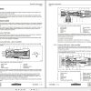
10 Hydraulic components
10.1 Variable displacement pump – Travel hydraulic
10.2 Variable displacement motor – Travel hydraulic
10.3 Regulating pump – Working hydraulic
10.4 Fixed displacement pump
10.5 Gear motor – Fan drive
10.6 Steering aggregate
10.7 Proportional control valve block
10.8 S / W control valve block
10.9 Brake cylinder
10.10 Valves
10.11 Hydraulic cylinder
11 Electrical system – Diagrams and components
11.1 Component description
11.2 Function list
11.3 Fuses and notes
11.4 Circuit diagram
11.5 Component arrangement
11.6 Control lever
11.7 Calibration of electronic load display
11.8 DMS Sensor Installation
12 Electrical system – Descriptions
12.1 Diagnostics Software Travel Hydraulic LinDiag
12.2 Software for Working hydraulic control Bodem
12.2 Software for Working hydraulic control BODAS
12.3 Service Code List
12.4 Software PDL – Diesel particle filter
13 Axles/ tires and gear shafts
13.1 Data page
13.2 Design of axles and gear shafts
13.3 Disk brake
13.4 Differential
13.5 Wheel hub with steering axle
13.6 Gear shafts
14 Main frame – Installations
14.1 Level regulation
14.2 Stabilizers / Side offset
14.3 Cooler arrangement
14.4 Engine mount
14.5 Battery installation
15 Tank arrangements
15.1 Hydraulic tank
15.2 Fuel tank
16 Operator’s cab, heater, air conditioning system
16.1 Operator’s cab
16.2 Heater with blower
16.3 Air conditioning system
17 Telescopic boom
17.1. Design and function
17.2 Repair instructions
17.3 Hose replacement in telescope
18 Working attachment
18.1. Tool coupler
18.2 Forklift
18.3 Bucket
18.4 Aerial work platform
19 Special Installations
19.1 Industrial control
19.2 Rear axle oscillation lock
19.4 Quick coupler
19.5 Reversible fan
19.6 Towing hitch device
19.7 Telescope – Leak oil line
20 Additional documentation
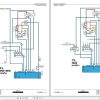
6.3 Schematic Travel hydraulic
7.3 Schematic Working hydraulic
8.3 Schematic Steering hydraulic
9.3 Schematic Brake hydraulic
11.4 Schematic Circuit diagram
14.1 Schematic Level regulation
14.2 Schematic Stabilizers and side offset
18.4 Schematic Aerial work platform
19.1 Schematic Industrial control
Related Products
-
Liebherr Wheeled and Crawler Excavators Updated 03.2022 Service Manuals DVD PDF
Original price was: 800.400Current price is: 400. USDLiebherr Wheeled and Crawler Excavators 48.3GB Updated 03.2022 Service Manuals DVD PDFSize: 48.3 GB (PDF Files)Format: PDFLanguage: EN, DEBrand: LiebherrDate Updated: 03.2022OS: All Windows 32 & 64bitType of Vehicle: Wheeled and Crawler ExcavatorsType of Document: Service ManualsHigh-Speed Link Download DETAIL CONTENTS: “CLICK HERE“Hot-50%
REALEASE :
02.03.2022
REALEASE :
02.03.2022
-
Liebherr Crawler Crane with Telescopic Boom LTR 1100 100 Ton Operator Manual Diagnostics LICCON Wiring Diagram
Original price was: 400.160Current price is: 160. USDLiebherr Crawler Crane with Telescopic Boom LTR 1100 100 Ton Operator Manual, Diagnostics LICCON & Wiring Diagram Size: 734 Mb Language: English_EN Format: PDF Model: LTR 1100 Capacity: 100 Ton SN: Z97542 Diesel Engine: D944 A7 DETAIL CONTENTS: “CLICK HERE“Hot-60%
REALEASE :
23.03.2022
REALEASE :
23.03.2022
-
Liebherr Wheel Loader Updated 03.2022 Full Service Manuals DVD PDF
Original price was: 700.400Current price is: 400. USDLiebherr Wheel Loader 24.29GB Updated 03.2022 Full Service Manuals DVD PDFSize: 24.29 GB (PDF Files)Type of Vehicle: Wheel LoadersType of Document: Service ManualsFormat: PDFLanguage: EN, ZH, DEBrand: LiebherrDate Updated: 03.2022OS: All Windows 32 & 64 bitHigh-Speed Link DownloadDETAIL CONTENTS: “CLICK HERE“Hot-43%
REALEASE :
02.03.2022
REALEASE :
02.03.2022
-
Liebherr Crane LTM 1800 Service Manual Operators Manual Schematic
Original price was: 300.180Current price is: 180. USDThey are PDF Service Manual Operators Manual Schematic Manual, You need to use these to repair your vehicle.Hot-40%
REALEASE :
16.09.2022
REALEASE :
16.09.2022
-
Liebherr Mining Excavators 84.88Gb PDF Updated 01.2022 Service Manuals DVD
USDLiebherr Mining Excavators 84.88Gb PDF Updated 01.2022 Service Manuals DVDSize: 84.88 Gb (PDF Files)Type of vehicle: Mining ExcavatorsType of manual: Service ManualLanguage: EnglishBrand: LiebherrFormat: PDFUpdate: 01.2022OS: All WindowsAmount of DVD: 1 DVDREALEASE :
01.13.2022
-
LIEBHERR LTM 1095-5.1 95 Ton Operator Manual Diagnostics LICCON Wiring Schematic PDF
Original price was: 200.60Current price is: 60. USDLIEBHERR LTM 1095-5.1 95 Ton Operator Manual, Diagnostics LICCON & Wiring DiagramSize: 77.3 MBFormat: PDFlanguage: EnglishBrand: LiebherrType of machine: Mobile CraneType of document:Model: LIEBHERR LTM 1095-5.1DETAIL CONTENTS: “CLICK HERE“Hot-70%
REALEASE :
25.03.2022
REALEASE :
25.03.2022
-
Liebherr Mobile Crawler Cranes PDF Spare Parts List DVD
Original price was: 200.140Current price is: 140. USDLiebherr Mobile & Crawler Cranes 1.24 GB PDF Spare Parts Catalog DVDSize: 1.24 GBFormat: PDF, winrarBrand: LiebherrLanguages: English, Deutsch, Spanish, Russian, French, PortugueseType of Machine: Mobile Crane, Crawler Crane, Rough Terrain Crane, Tower CraneType of Document: Spare Parts CatalogsNumber of DVD: 1 DVDOS: Windows Vista, XP, 7, 8.1, 8, 10, MacOSHigh-Speed DownloadDETAIL CONTENTS: “CLICK HERE“Hot-30%
REALEASE :
29.03.2022
REALEASE :
29.03.2022
-
Liebherr Crane HS HSG Operating Manual Spare Parts List Technical Information PDF DVD
Original price was: 1,500.600Current price is: 600. USDLiebherr Crane HS HSG Operating Manual Spare Parts Catalogue Technical Information DVD Size: 2.17 GB Fomat: PDF Language: EN,DE Brand: Liebherr Type of machine: Liebherr Crawler Crane Window: All Win 32 and 64 Bit, Mac OS Type of document: Liebherr Crane HS Operating Manual Liebherr Crane HS Spare Parts Catalogue Liebherr Crane HS Technical information Liebherr Crane HS Electrical Circuit Diagram Liebherr Crane HS Hydraulic Circuit DiagramHot-60%
REALEASE :
04.07.2022
REALEASE :
04.07.2022
