
0 ITEMSVIEW CART

✓
Expert Support
✓
Full Speed
✓
100% Working
Liebherr Telescopic Handler T60-9-1709_3AS Service Manual 12261273 2023
Size: 104.50 MB
Format: PDF
Language: English
Brand: Liebherr
Type of Machine: Telescopic Handler
Type of Manual: Service Manual, Electric and Hydraulic Diagrams
Model: Liebherr T60-9-1709_3AS Telescopic Handler
Order Number: 12261273
Publication Date: 2023
Number of Pages: 1712 Pages
150 USD
- Description
Description
Contents:
010 Introduction
010.1 Safety instructions
010.2 Special tools for maintenance and repair work
010.3 Standards and specifications
010.4 Conservation guidelines
010.5 Repair welding
010.6 Hydraulic symbols
010.7 Electrical symbols
010.8 Material weights
020 Technical data
020.1 Complete machine
020.2 Drive group
020.3 Cooling system
020.4 Working hydraulics
020.5 Travel hydraulics
020.6 Hydraulic components
020.7 Electrical system
020.8 Travel gear, axles, tyres, drive shafts
020.9 Steel components Basic machine
030 Maintenance
030.1 General information on the maintenance and inspection schedule
030.2 Maintenance and inspection schedule
030.3 Fill quantities and lubrication chart
030.4 Lubricants and fuels
030.5 Maintenance tasks
030.6 Adjustment checklist
030.7 Adjustment procedure
040 Drive group
040.1 Diesel engine
040.2 Clutch
050 Cooling system
050.1 Cooling system – Full overview
050.2 Cooling system – Full overview
060 Working hydraulics
060.1 Working hydraulics – Full overview
060.2 Working hydraulics – Full overview
060.3 Working hydraulics – Full overview
060.4 Regulating pump
060.5 Proportional control valve block
060.6 Working hydraulic pilot control unit
070 Travel hydraulics
070.1 Travel hydraulics – Full overview
070.2 Travel hydraulics – Full overview
070.3 Variable displacement pump
070.4 Variable displacement motors
080 Hydraulic components
080.1 Hydraulic system – Full overview
080.2 Hydraulic system – Full overview
080.3 Hydraulic system – Full overview
080.4 Valves
080.5 Hydraulic tank
090 Steering system
090.1 Steering system – Full overview
090.2 Steering system – Full overview
090.3 Steering system – Full overview
090.4 Priority valve
090.5 Steering aggregate
100 Brake system
100.1 Brake system – Full overview
100.2 Brake system – Full overview
100.3 Inching brake pedal
110 Electrical system
110.1 Electrical system – Full overview
110.2 Electrical system – Full overview
110.3 Electrical system – Full overview
110.4 Lighting – Full overview
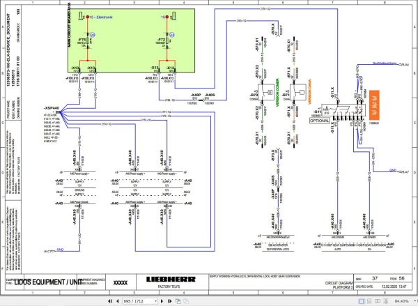
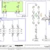
110.5 Circuit diagrams
110.6 Electrical components of operator’s cab
110.7 Electrical components of diesel engine – Full overview (emission stage III-A)
110.8 Electrical components of diesel engine – Full overview (emission stage III-A)
110.9 Electrical components of diesel engine – Full overview (emission stage V/tier 4f)
110.10 Electrical system – Telescope – Full overview
110.11 Telescope socket, 4-pin
110.12 Electrical components of automatic retraction of telescope
110.13 Electrical components of automatic bucket repositioning
110.14 Electrical components Compartments
110.15 Display unit
110.16 Option package 2 – Full overview
110.17 Option package 2 – Full overview
110.18 Option package 2 – Full overview
110.19 Electrical components of Liebherr telematics unit
110.20 CAN communication
110.21 Electrical components for fuel preheating 12 V
110.22 Electrical components of cameras
110.23 Electrical components of cameras
110.24 Electrical components of cameras
130 Travel gear, axles, tyres, drive shafts
130.1 Axles and drive shafts
130.2 Multiple disc brake
130.3 Differential gear
130.4 Wheel hub and steering axle
130.5 Drive shaft
130.6 DMS sensor installation
130.7 Overload warning device
140 Steel components Basic machine
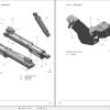
140.1 Telescopic boom 9 m (29.5 ft)
160 Operator’s cab, heating and air conditioning
160.1 Operator’s platform
160.2 Operator’s cab
160.3 Heating, ventilation, air conditioning
170 Lubrication system
170.1 Standard lubrication system – Full overview
170.2 Manual central lubrication system
170.3 Automatic central lubrication system
190 Options
190.1 Automatic dust discharge (option)
190.2 Reversible fan drive
190.3 Reversible fan drive
190.4 4×4 shut-off
190.5 4×4 shut-off
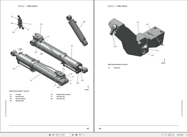
190.6 Ride control
190.7 Ride control
190.8 Ride control
190.9 Emergency down
190.10 Emergency down
190.11 Hydraulic trailer brake – 2-line
190.12 Hydraulic trailer brake – 2-line
190.13 Hydraulic trailer brake – 2-line
190.14 Electrically reversible control circuit 3
190.15 Electrically reversible control circuit 3
190.16 Electrically reversible control circuit 3
190.17 High flow control circuit 3
190.18 High flow control circuit 3
190.19 High flow control circuit 3
190.20 Control circuit 3 leak oil line
190.21 Control circuit 3 leak oil line
190.22 Control circuit 3 leak oil line
190.23 Liebherr quick coupler
190.24 Liebherr quick coupler
190.25 Liebherr quick coupler
190.26 Manitou quick coupler
190.27 Manitou quick coupler
190.28 Manitou quick coupler
190.29 Scorpion quick coupler
190.30 Scorpion quick coupler
190.31 Scorpion quick coupler
190.32 JCB Q-FIT quick coupler
190.33 JCB Q-FIT quick coupler
190.34 JCB Q-FIT quick coupler
190.35 Control circuit 4 tipper connection
190.36 Control circuit 4 tipper connection
190.37 Control circuit 4 tipper connection
190.38 Tipper and rear hydraulics control circuit 4
190.39 Tipper and rear hydraulics control circuit 4
190.40 Tipper and rear hydraulics control circuit 4
190.41 Trailer coupling, tipper and rear hydraulics control circuit 4
190.42 Trailer coupling, tipper and rear hydraulics control circuit 4
190.43 Trailer coupling, tipper and rear hydraulics control circuit 4
190.44 Rear axle pendulum lock
190.45 Rear axle pendulum lock
190.46 Rear axle pendulum lock
190.47 Air brake system – Full overview
190.48 Working hydraulics fine control (option)
190.49 Function
200 Service codes, diagnosis
200.1 Malfunctions
200.2 Test and adjustment software
Related Products
-
Liebherr Crane HS HSG Operating Manual Spare Parts List Technical Information PDF DVD
Original price was: 1,500.540Current price is: 540. USDLiebherr Crane HS HSG Operating Manual Spare Parts Catalogue Technical Information DVD Size: 2.17 GB Fomat: PDF Language: EN,DE Brand: Liebherr Type of machine: Liebherr Crawler Crane Window: All Win 32 and 64 Bit, Mac OS Type of document: Liebherr Crane HS Operating Manual Liebherr Crane HS Spare Parts Catalogue Liebherr Crane HS Technical information Liebherr Crane HS Electrical Circuit Diagram Liebherr Crane HS Hydraulic Circuit DiagramHot-64%
REALEASE :
04.07.2022
REALEASE :
04.07.2022
-
Liebherr Crane LTM 1800 Service Manual Operators Manual Schematic
Original price was: 300.180Current price is: 180. USDThey are PDF Service Manual Operators Manual Schematic Manual, You need to use these to repair your vehicle.Hot-40%
REALEASE :
16.09.2022
REALEASE :
16.09.2022
-
Liebherr Crawler Crane with Telescopic Boom LTR 1100 100 Ton Operator Manual Diagnostics LICCON Wiring Diagram
Original price was: 400.160Current price is: 160. USDLiebherr Crawler Crane with Telescopic Boom LTR 1100 100 Ton Operator Manual, Diagnostics LICCON & Wiring Diagram Size: 734 Mb Language: English_EN Format: PDF Model: LTR 1100 Capacity: 100 Ton SN: Z97542 Diesel Engine: D944 A7 DETAIL CONTENTS: “CLICK HERE“Hot-60%
REALEASE :
23.03.2022
REALEASE :
23.03.2022
-
Liebherr Mining Excavators 84.88Gb PDF Updated 01.2022 Service Manuals DVD
USDLiebherr Mining Excavators 84.88Gb PDF Updated 01.2022 Service Manuals DVDSize: 84.88 Gb (PDF Files)Type of vehicle: Mining ExcavatorsType of manual: Service ManualLanguage: EnglishBrand: LiebherrFormat: PDFUpdate: 01.2022OS: All WindowsAmount of DVD: 1 DVDREALEASE :
01.13.2022
-
LIEBHERR LTM 1095-5.1 95 Ton Operator Manual Diagnostics LICCON Wiring Schematic PDF
Original price was: 200.60Current price is: 60. USDLIEBHERR LTM 1095-5.1 95 Ton Operator Manual, Diagnostics LICCON & Wiring DiagramSize: 77.3 MBFormat: PDFlanguage: EnglishBrand: LiebherrType of machine: Mobile CraneType of document:Model: LIEBHERR LTM 1095-5.1DETAIL CONTENTS: “CLICK HERE“Hot-70%
REALEASE :
25.03.2022
REALEASE :
25.03.2022
-
Liebherr Mobile Crawler Cranes PDF Spare Parts List DVD
Original price was: 200.140Current price is: 140. USDLiebherr Mobile & Crawler Cranes 1.24 GB PDF Spare Parts Catalog DVDSize: 1.24 GBFormat: PDF, winrarBrand: LiebherrLanguages: English, Deutsch, Spanish, Russian, French, PortugueseType of Machine: Mobile Crane, Crawler Crane, Rough Terrain Crane, Tower CraneType of Document: Spare Parts CatalogsNumber of DVD: 1 DVDOS: Windows Vista, XP, 7, 8.1, 8, 10, MacOSHigh-Speed DownloadDETAIL CONTENTS: “CLICK HERE“Hot-30%
REALEASE :
29.03.2022
REALEASE :
29.03.2022
-
Liebherr Wheel Loader Updated 03.2022 Full Service Manuals DVD PDF
Original price was: 700.340Current price is: 340. USDLiebherr Wheel Loader 24.29GB Updated 03.2022 Full Service Manuals DVD PDFSize: 24.29 GB (PDF Files)Type of Vehicle: Wheel LoadersType of Document: Service ManualsFormat: PDFLanguage: EN, ZH, DEBrand: LiebherrDate Updated: 03.2022OS: All Windows 32 & 64 bitHigh-Speed Link DownloadDETAIL CONTENTS: “CLICK HERE“Hot-51%
REALEASE :
02.03.2022
REALEASE :
02.03.2022
-
Liebherr Wheeled and Crawler Excavators Updated 03.2022 Service Manuals DVD PDF
Original price was: 800.340Current price is: 340. USDLiebherr Wheeled and Crawler Excavators 48.3GB Updated 03.2022 Service Manuals DVD PDFSize: 48.3 GB (PDF Files)Format: PDFLanguage: EN, DEBrand: LiebherrDate Updated: 03.2022OS: All Windows 32 & 64bitType of Vehicle: Wheeled and Crawler ExcavatorsType of Document: Service ManualsHigh-Speed Link Download DETAIL CONTENTS: “CLICK HERE“Hot-58%
REALEASE :
02.03.2022
REALEASE :
02.03.2022
