
17 ITEMSVIEW CART


Total: 545.00
Expert Support
Full Speed
100% Working
100 USD
Contents:
1 General
1.01 Introduction
2 Accident prevention
2.02 Accident Prevention Guidelines
3 Tables, Data
3.01 Conversion Chart
3.02 Tightening Torques
3.03 ISO-Toleranzen
3.04 Material Classification
4 Special tools
4.01 General special Tools for Wheel loader
4.02 Special Tools for LIEBHERR Engine
4.04 Special Tools for electric
4.06 Special Tools for ZF – Axles
4.08 Special Tools for ZF – Powershift transmission
5 Welding
5.02 Repair Welding
6 Lubricants
6.01 General, Lubrication an Operating Fluids
6.11 Lubrication chart
7 Specifications / Inspection plan
7.02 Adjustment Checklist L511
7.02 Adjustment Checklist L521
7.02 Adjustment Checklist L531
7.02 Adjustment Checklist L541
7.08 Technical Data L511
7.09 Technical Data L521
7.10 Technical Data L531
7.11 Technical Data L541
7.18 Inspection Schedule L511
7.19 Inspection Schedule L521
7.20 Inspection Schedule L531
7.21 Inspection Schedule L541
7.25 Traction diagram
7.30 Maintenance and Inspections
8 Diesel Engine / Clutch
8.05 Liebherr Diesel Engine L511, L521, L531
8.06 Liebherr Engine L541
8.10 Deutz Engine L531, L541 from 101
8.20 Solenoid / Engine shut off
8.30 Clutch
9 Pump Distributor Gear
9.10 Description with drawing of the gear box L531 / L541 from 101
9.11 Description with drawing of de gear box L531 / L541 from 501
10 Travelling hydraulic
10.02 Operating pressure L511 / L521
10.03 Operating pressure L531 / L541
10.08 Travel hydraulic system L511 / L521
10.11 Travel hydraulic system L531 / L541
10.30 Hydraulic pump A4V
10.38 Block curve / travell system L511
10.39 Block curve / travell system L521
10.40 Block curve / travell system L531 / L541
10.48 Hydraulic motor A6VM
10.71 Regulator valve
10.74 Replenishing pressure relief valve
10.76 Crossover relief valve
10.78 Pressure cut off valve
10.80 Inching valve
10.90 Towing procedure
11 Working hydraulic
11.02 Working pressure L511 / L521
11.03 Working pressure L531 / L541
11.08 Working hydraulic – appliance L511 / L521 from 101
11.11 Working hydraulic – appliance L531 / L541 from 501
11.28 Variable displacement pump A10V
11.30 Variable dispacement pump A7V
11.38 Pump performance diagramm L511
11.39 Pump performance diagramm L521
11.40 Pump performance diagramm L531 / L541
11.41 Pump performance diagramm L541 from 501
11.50 Control valve-block, General information, leakage oil information
11.53 Control valve-block NG 16/NG 22
11.60 Pressure relief-valve direct controlled
11.62 Pressure relief-valve pilot controlled
11.64 Pressure relief-valve with suction valve function
11.66 Throttle – Check valve
11.68 Bleeder valve
11.70 Thermostatic valve
11.78 Servo control L511 / L521 from 101
11.81 Servo control L531 / L541 from 501
11.84 Pilot control valve L511 / L521 from 101
11.85 Pilot control valve L531 / L541 from 101
11.90 Hydraulic Cylinder
12 Electrical System
12.01 Electrical System, General Information
12.02 Battery
12.03 Starter
12.04 Alternator
12.05 Pre-heating System
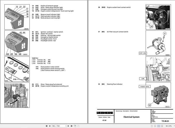
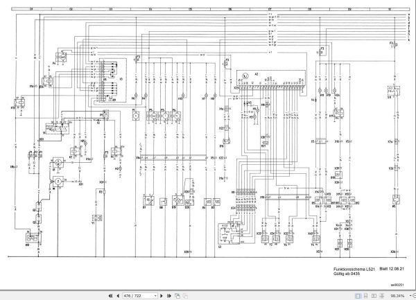
12.08 Electrical System
12.10 Electrical System L531 / L514 from 101
12.20 Instrument / Tachometer / Diode board / Relay / Fuses
12.30 Proximity switch
13 Heater / Air conditioning
13.05 Single circuit heater
14 Transmission
14.08 Powershift transmission 2 AVG 110
14.10 Powershift transmission 3 AVG 200 / 210
14.11 Shifting Unit 3 AVG 210
14.12 Troubleshooting
14.20 Electronic control unit
14.30 Bypass – Valve
15 Axles / Tires
15.01 Axles – General
15.10 Differential
15.30 Wheel head
16 Steering
16.01 General Data
16.10 Hydraulic Steering System
16.20 Valve Block
16.30 Servostat
16.40 Servo Control Valve
16.50 Steering Cylinder
17 Brakes
17.01 General Information
17.10 Hydraulic Brake System
17.20 Cut Off Valve
17.30 Service Brake Valve
17.40 Parking Brake Valve
18 Main frame / Operator´s cab
18.10 Description of Removal / Installation of Articulation and Oscillating Axle
18.20 Description and Construction of Cab
19 Lift frame / Accessories
19.01 Lift Arms
19.09 Lift Arms, Check stops / tilt angle
19.10 Special lift arms
20 Optional Equipment
20.01 Attachment – Snow Remover
20.02 Attachment – Front section / Manual control
20.04 Hydraulic Quick Change Coupling

REALEASE :
25.03.2022
REALEASE :
25.03.2022

REALEASE :
29.03.2022
REALEASE :
29.03.2022

REALEASE :
16.09.2022
REALEASE :
16.09.2022
REALEASE :
01.13.2022

REALEASE :
02.03.2022
REALEASE :
02.03.2022

REALEASE :
23.03.2022
REALEASE :
23.03.2022

REALEASE :
04.07.2022
REALEASE :
04.07.2022

REALEASE :
02.03.2022
REALEASE :
02.03.2022
 Automotive - Heavy Equipment - Truck & Bus - Forklift - Crane