
0 ITEMSVIEW CART

✓
Expert Support
✓
Full Speed
✓
100% Working
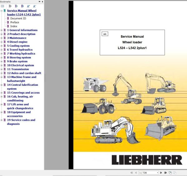
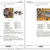
Liebherr Wheel Loader L524 to L542 2plus1 Service Manual 10411314
Size: 39.62 MB
Format: PDF
Language: English
Brand: Liebherr
Type of Machine: Wheel Loader
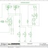
Type of Manual: Service Manual, Electric and Hydraulic Diagrams
Model: Liebherr
L524 S/N 17890
L528 S/N 17891
L538 S/N 17893
L542 S/N 17895
Engine: Liebherr D 504 TI / John Deere CD 4045 (Tier 3 – Stage III-A)
Order Number: 10411314
Number of Pages: 726 Pages
100 USD
- Description
Description
Contents:
1 General informations
1.1 Safety regulations
1.2 Special tools for maintenance andrepair work
1.3 Standard
2 Product description
2.1 Technical data
3 Maintenance
3.1 Maintenance and inspection schedule
3.2 Testing and adjustment plan
3.3 Testing and adjustment checklists
3.4 Lubrication chart and filling quantities
3.5 Maintenance tasks
3.6 Testing and adjustment tasks
3.7 Lubricants and fuels
4 Diesel engine
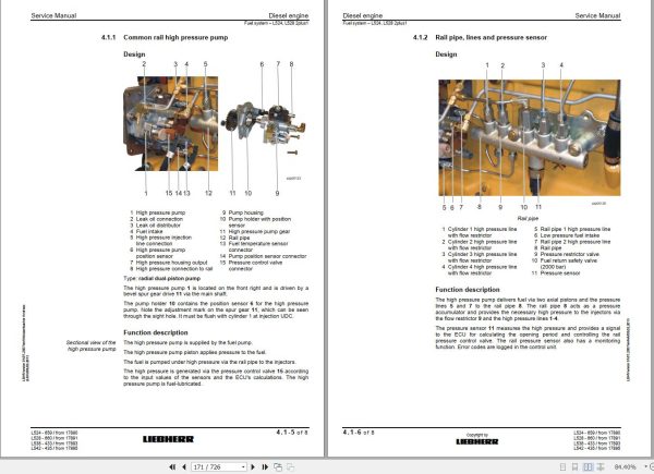
4.1 Diesel engine – L524, L528 2plus1
4.2 Electrical components of the dieselengine – L524, L528 2plus1
4.3 Fuel system – L524, L528 2plus1
4.4 Diesel engine – L538, L542 2plus1
4.5 Electrical components of thediesel engine – L538, L542 2plus1
4.6 Fuel system – L538, L542 2plus1
4.7 Air filter system
4.8 Exhaust system
4.9 Coupling
5 Cooling system
5.1 Cooling system
5.2 Gear pump
5.3 Gear motor
5.4 Temperature sensors
6 Travel hydraulics
6.1 Travel hydraulics
6.2 Variable displacement pump
6.3 Variable displacement motors
7 Working hydraulics
7.0.1 Working hydraulics L524, L528
7.0.2 Working hydraulics L538, L542
7.1 Working hydraulics pump
7.2 Control block
7.3 Pilot control
7.4 Ride control
7.5 Lift and tilt cylinders
7.6 Hydraulic tank
8 Steering system
8.0.1 Steering system L524, L528
8.0.2 Steering system L538, L542
8.1 Steering pump
8.2 Servostat
8.3 Steering cylinder
8.4 Emergency steering
9 Brake system
9.1 Brake system
9.2 Service brake
9.3 Parking brake
10 Electrical system
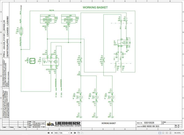
10.1 Electrical system with circuit diagrams
L524, L528 93010028-303
L538, L542 93010027-303
10.2 Electrical components
10.3 Master controller – UC3 (UniversalEarth Mover Controller 3)
10.4 Battery installation
11 Transmission
11.1 Transmission
11.2 Mechanical transmission
11.3 Electronic control unit
12 Axles and cardan shaft
12.1 Front axle
12.2 Rear axle
12.3 Cardan shaft
13 Machine frame and ballastweight
13.1 Machine frame
13.2 Articulation bearing
13.3 Articulation lock
13.4 Ballast weight
14 Central lubrification system
14.1 Manual central lubrication
14.2 LIEBHERR automatic centrallubrication system (optional)
15 Coverings and access
15.1 Coverings
15.2 Cab access
16 Cab, heating, air conditioning
16.1 Cab, heating and air-conditioning
16.2 Instrument panel
16.3 Heating, ventilation, air conditioning
16.4 Air conditioning system (optional)
17 Lift arms and quick-changedevice
17.1 Lift arms with Z kinematics
17.2 Lift arms with P kinematics
17.3 Hydraulic quick-change device forZ lift arms
17.4 Hydraulic quick-change device forP lift arms
18 Equipment and accessories
18.1 Loading bucket
18.2 Forklift
18.3 Connection sizes
19 Service codes and diagnosis
19.1 Malfunctions
Related Products
-
Liebherr Mining Excavators 84.88Gb PDF Updated 01.2022 Service Manuals DVD
USDLiebherr Mining Excavators 84.88Gb PDF Updated 01.2022 Service Manuals DVDSize: 84.88 Gb (PDF Files)Type of vehicle: Mining ExcavatorsType of manual: Service ManualLanguage: EnglishBrand: LiebherrFormat: PDFUpdate: 01.2022OS: All WindowsAmount of DVD: 1 DVDREALEASE :
01.13.2022
-
Liebherr Mobile Crawler Cranes PDF Spare Parts List DVD
Original price was: 200.140Current price is: 140. USDLiebherr Mobile & Crawler Cranes 1.24 GB PDF Spare Parts Catalog DVDSize: 1.24 GBFormat: PDF, winrarBrand: LiebherrLanguages: English, Deutsch, Spanish, Russian, French, PortugueseType of Machine: Mobile Crane, Crawler Crane, Rough Terrain Crane, Tower CraneType of Document: Spare Parts CatalogsNumber of DVD: 1 DVDOS: Windows Vista, XP, 7, 8.1, 8, 10, MacOSHigh-Speed DownloadDETAIL CONTENTS: “CLICK HERE“Hot-30%
REALEASE :
29.03.2022
REALEASE :
29.03.2022
-
Liebherr Crane HS HSG Operating Manual Spare Parts List Technical Information PDF DVD
Original price was: 1,500.540Current price is: 540. USDLiebherr Crane HS HSG Operating Manual Spare Parts Catalogue Technical Information DVD Size: 2.17 GB Fomat: PDF Language: EN,DE Brand: Liebherr Type of machine: Liebherr Crawler Crane Window: All Win 32 and 64 Bit, Mac OS Type of document: Liebherr Crane HS Operating Manual Liebherr Crane HS Spare Parts Catalogue Liebherr Crane HS Technical information Liebherr Crane HS Electrical Circuit Diagram Liebherr Crane HS Hydraulic Circuit DiagramHot-64%
REALEASE :
04.07.2022
REALEASE :
04.07.2022
-
Liebherr Crawler Crane with Telescopic Boom LTR 1100 100 Ton Operator Manual Diagnostics LICCON Wiring Diagram
Original price was: 400.160Current price is: 160. USDLiebherr Crawler Crane with Telescopic Boom LTR 1100 100 Ton Operator Manual, Diagnostics LICCON & Wiring Diagram Size: 734 Mb Language: English_EN Format: PDF Model: LTR 1100 Capacity: 100 Ton SN: Z97542 Diesel Engine: D944 A7 DETAIL CONTENTS: “CLICK HERE“Hot-60%
REALEASE :
23.03.2022
REALEASE :
23.03.2022
-
Liebherr Wheel Loader Updated 03.2022 Full Service Manuals DVD PDF
Original price was: 700.340Current price is: 340. USDLiebherr Wheel Loader 24.29GB Updated 03.2022 Full Service Manuals DVD PDFSize: 24.29 GB (PDF Files)Type of Vehicle: Wheel LoadersType of Document: Service ManualsFormat: PDFLanguage: EN, ZH, DEBrand: LiebherrDate Updated: 03.2022OS: All Windows 32 & 64 bitHigh-Speed Link DownloadDETAIL CONTENTS: “CLICK HERE“Hot-51%
REALEASE :
02.03.2022
REALEASE :
02.03.2022
-
Liebherr Crane LTM 1800 Service Manual Operators Manual Schematic
Original price was: 300.180Current price is: 180. USDThey are PDF Service Manual Operators Manual Schematic Manual, You need to use these to repair your vehicle.Hot-40%
REALEASE :
16.09.2022
REALEASE :
16.09.2022
-
Liebherr Wheeled and Crawler Excavators Updated 03.2022 Service Manuals DVD PDF
Original price was: 800.340Current price is: 340. USDLiebherr Wheeled and Crawler Excavators 48.3GB Updated 03.2022 Service Manuals DVD PDFSize: 48.3 GB (PDF Files)Format: PDFLanguage: EN, DEBrand: LiebherrDate Updated: 03.2022OS: All Windows 32 & 64bitType of Vehicle: Wheeled and Crawler ExcavatorsType of Document: Service ManualsHigh-Speed Link Download DETAIL CONTENTS: “CLICK HERE“Hot-58%
REALEASE :
02.03.2022
REALEASE :
02.03.2022
-
LIEBHERR LTM 1095-5.1 95 Ton Operator Manual Diagnostics LICCON Wiring Schematic PDF
Original price was: 200.60Current price is: 60. USDLIEBHERR LTM 1095-5.1 95 Ton Operator Manual, Diagnostics LICCON & Wiring DiagramSize: 77.3 MBFormat: PDFlanguage: EnglishBrand: LiebherrType of machine: Mobile CraneType of document:Model: LIEBHERR LTM 1095-5.1DETAIL CONTENTS: “CLICK HERE“Hot-70%
REALEASE :
25.03.2022
REALEASE :
25.03.2022
